

Physical Vapor Deposition (PVD) encompasses techniques for vaporizing a substance and depositing it onto a surface. Unlike electroplating, PVD can coat non-conductive materials. avoid the use of unsafe electrolyte solutions in general (such as a cyanide used for plating gold).
My goal is to coat glass microscope slides with a film of copper metal. I have some ideas for how I will use these copper slides but I’ll save it for another time…
The principle of magnetron sputtering
How Magnetron Sputtering Works
To vaporize copper, imagine it’s surface as a line of billiard balls at an atomic scale. If you hit one shooter ball into the line, its momentum transfers to the ball it strikes, causing that target ball to fly away from the group.

Argon is going to be our shooter ball as it’s an inert/noble gas and won’t react with copper. If we used something like oxygen gas, then the target copper atoms would combine into Copper Oxides. Coating our microscope slide with a non-conductive rust. Which may or may not be useful, but it isn’t my goal right now.
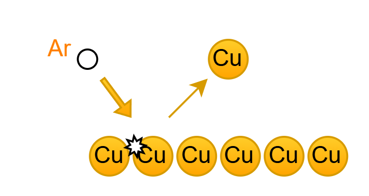
If we were able to put opposite charges on the argon “shooter” and the copper target, then the argon would be attracted to the target and smash into it.
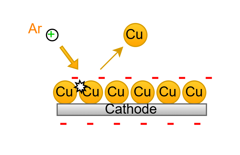
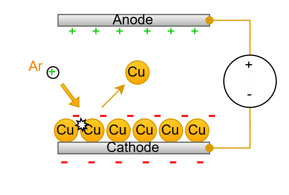
We can use a high voltage DC supply and connect the copper to the negative terminal supply.
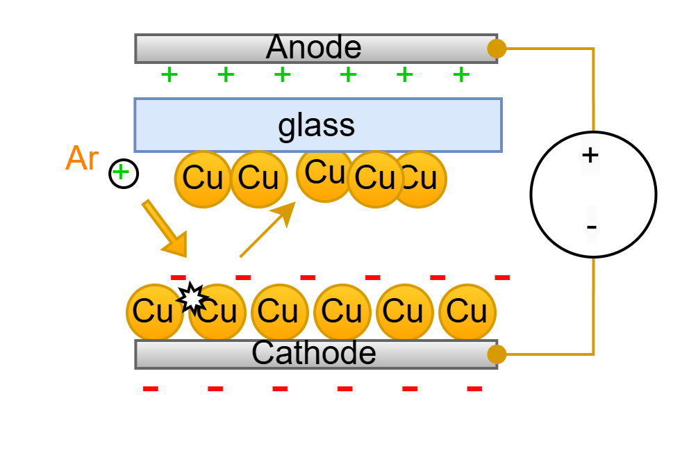
If we put the thing that we want to coat in front of the barrage of copper sputtering, then it will eventually become coated with copper!
Now the problem lies in giving Argon a charge. Since Argon is a noble gas, it has a full outer shell of 8 electrons, it has all the electrons that it would ever want. No electron lust.

However, if we provide enough energy (1520.6 kJ/mol or 15.76 eV) to argon’s valence electron, it will be removed from the atom. This can happen when a high-energy electron collides with the valence electron and transfers its energy. This process is known as electron ionization: Ar + e- → Ar+ + 2e-
The follow up question is how do we collide high energy electrons into argon?
For those that don’t know. There are these things called magnets. They’re very underrated.
The magnetic force on moving charged particles is known as the Lorentz Force. The equation is as follows (alongside the direction of vectors from three different angles).
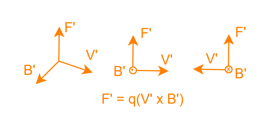
If you have a charged particle moving in a direction within a magnetic field (B), there will be a force enacted onto the charge in the direction of the cross product of the B field and V vectors (B’, v’).
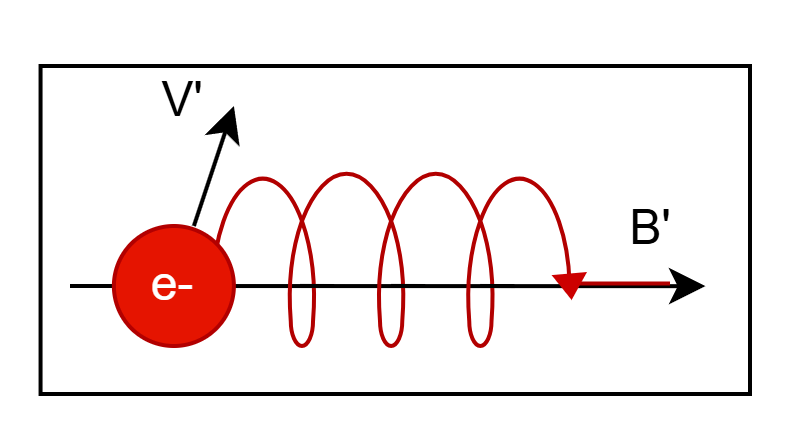
The key result of this phenomenon is that when an electron is moving normal to a magnetic field, it will start to spiral along the field thanks to Lorentz force.
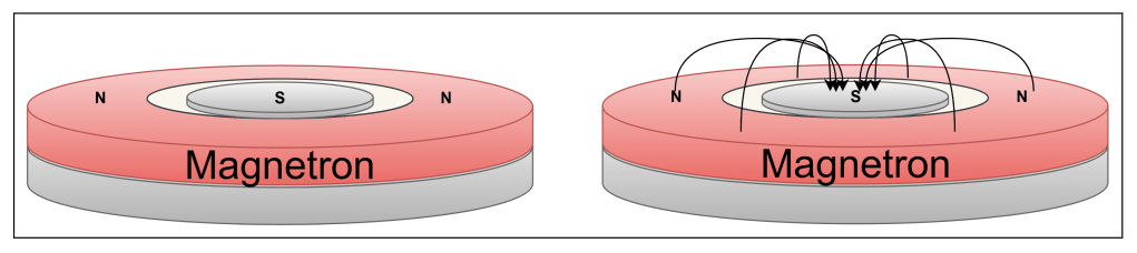
By taking a ring magnet and cylindrical magnet of a flipped polarity. You can make a semi-torus shaped magnetic field, like the top half of a bagel. This is the magnetron in magnetron sputtering.
This shape of this magnetic field will trap some electrons that are trying to move to the anode as shown below:
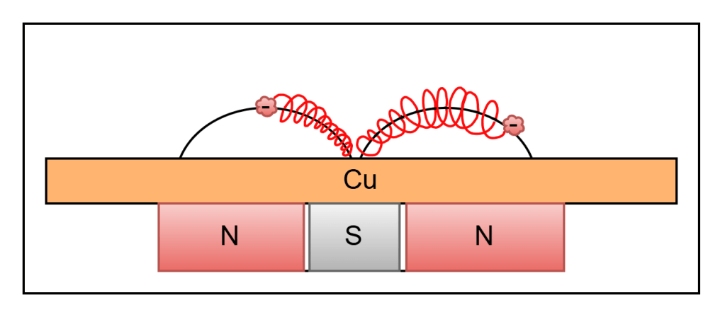
If we replace the air with low pressure argon gas, then there’s a chance one of the argon atoms will collide into a spinning electron and form an argon cation.
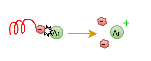
Then the charged argon will speed into the copper target, causing copper to sputter out.
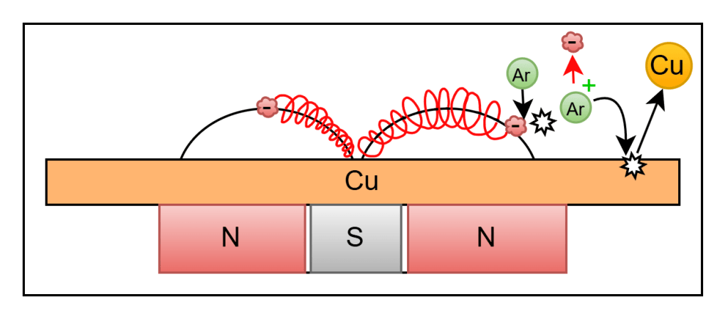
Adding the magnetron to our earlier diagram:
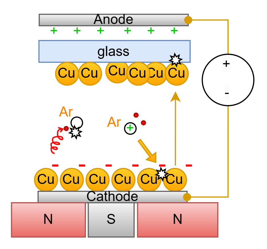
First Attempt:
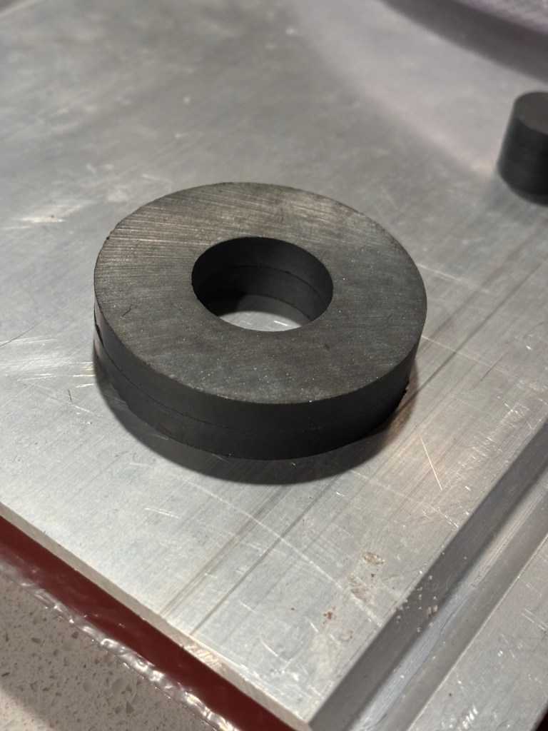
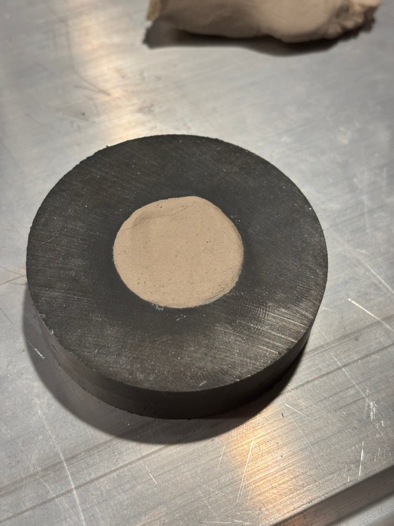
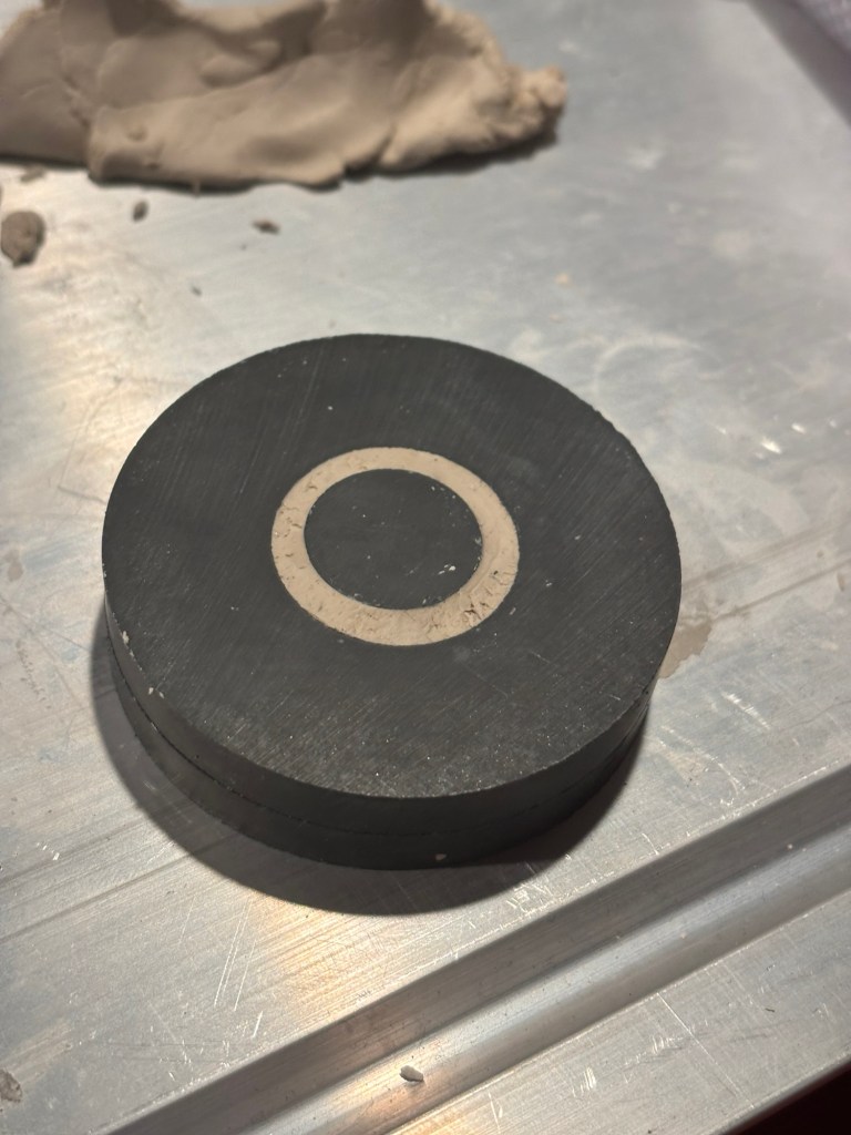
To build the magnetron, I bought two ferromagnetic rings, stacked them, filled the center with Crayola air-dry clay, and added a stack of three cylindrical magnets to be coaxial with the outer ring. The stack of three cylindrical magnets only served to match the height of the ring magnet.
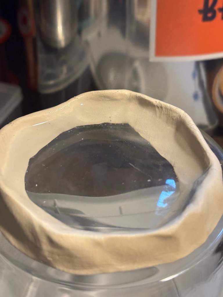
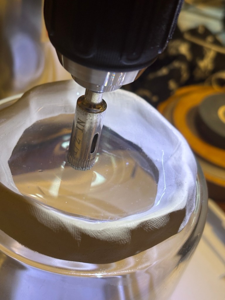
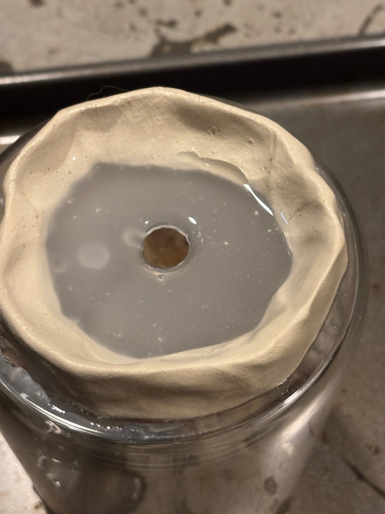
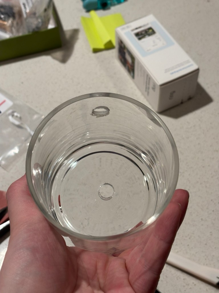
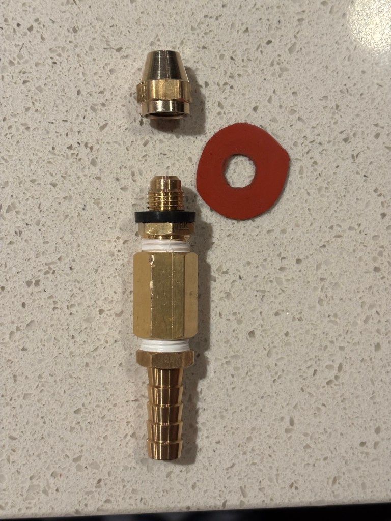
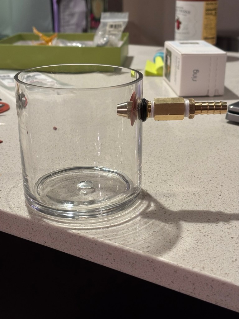
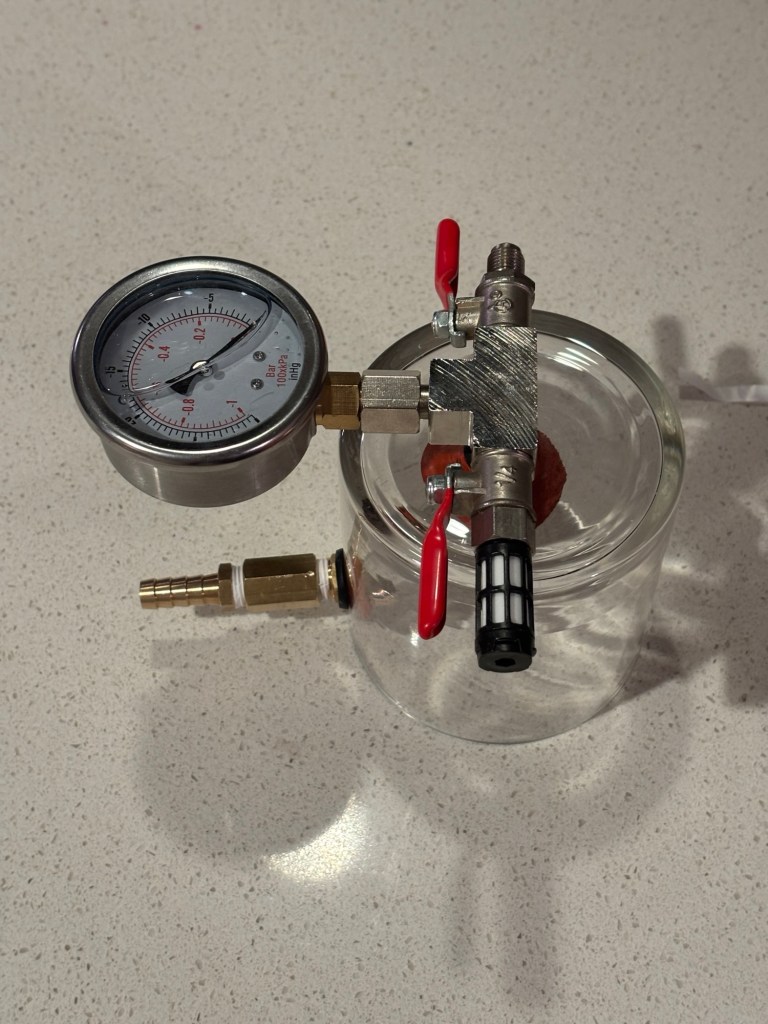
To make a DIY vacuum chamber, I used a thick glass jar and molded air-dry clay into a bowl filled with water to cool it while drilling. I drilled a hole for a vacuum hose adapter fitting, starting at a 45-degree angle and then slowely moved the drill bit perpendicular to the glass as I drilled.
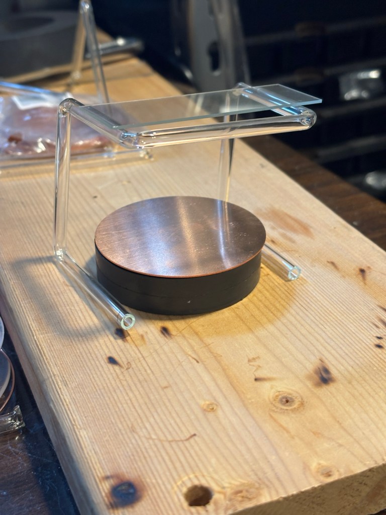
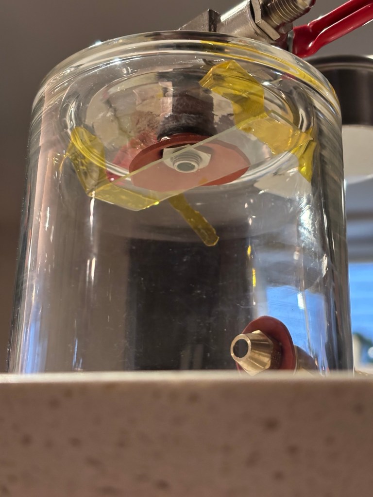
I then bent a glass rod (leftover from a failed cold plasma needle) to hold the microscope slide above the plasma.
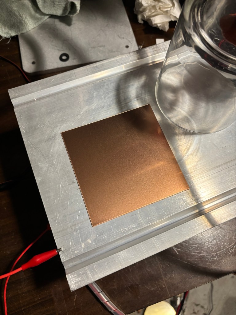
Assembly started with taking a copper plate that is larger than the radius of the glass jar. This will be our target. The aluminum metal below it will hopefully act as a heatsink as the magnets will get very hot during operation.
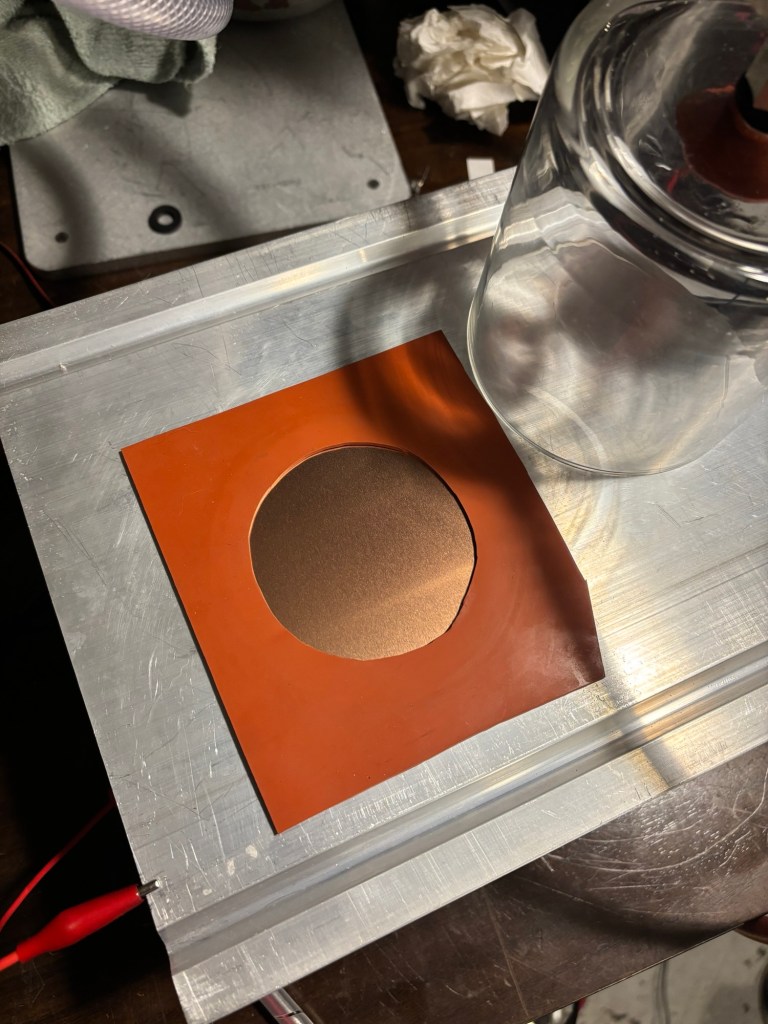
Then a DIY silicone sheet gasket was placed on top of the copper
The glass slide holder was then placed.
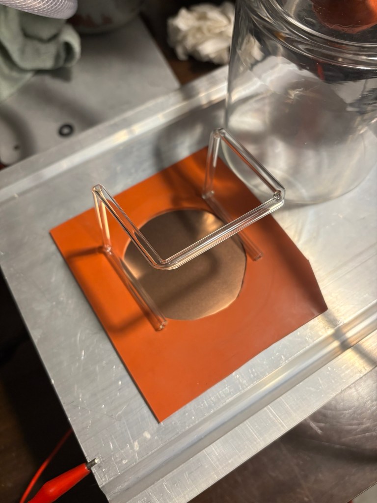
then the microscope slide was placed on the holder.
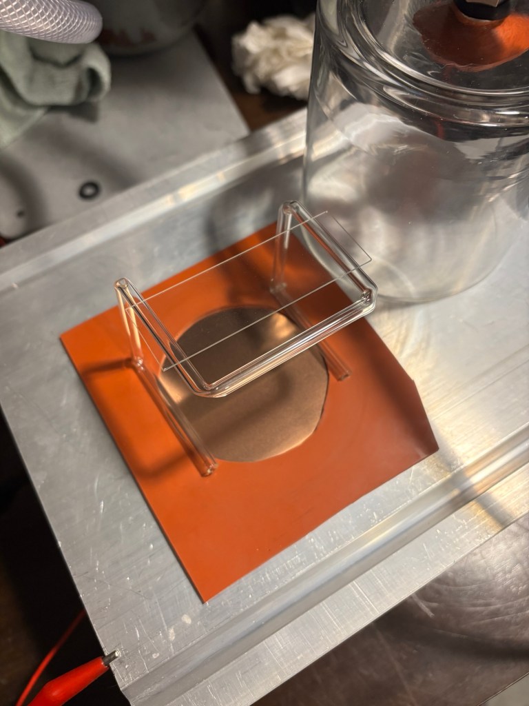
The jar was placed on top of the assembly.
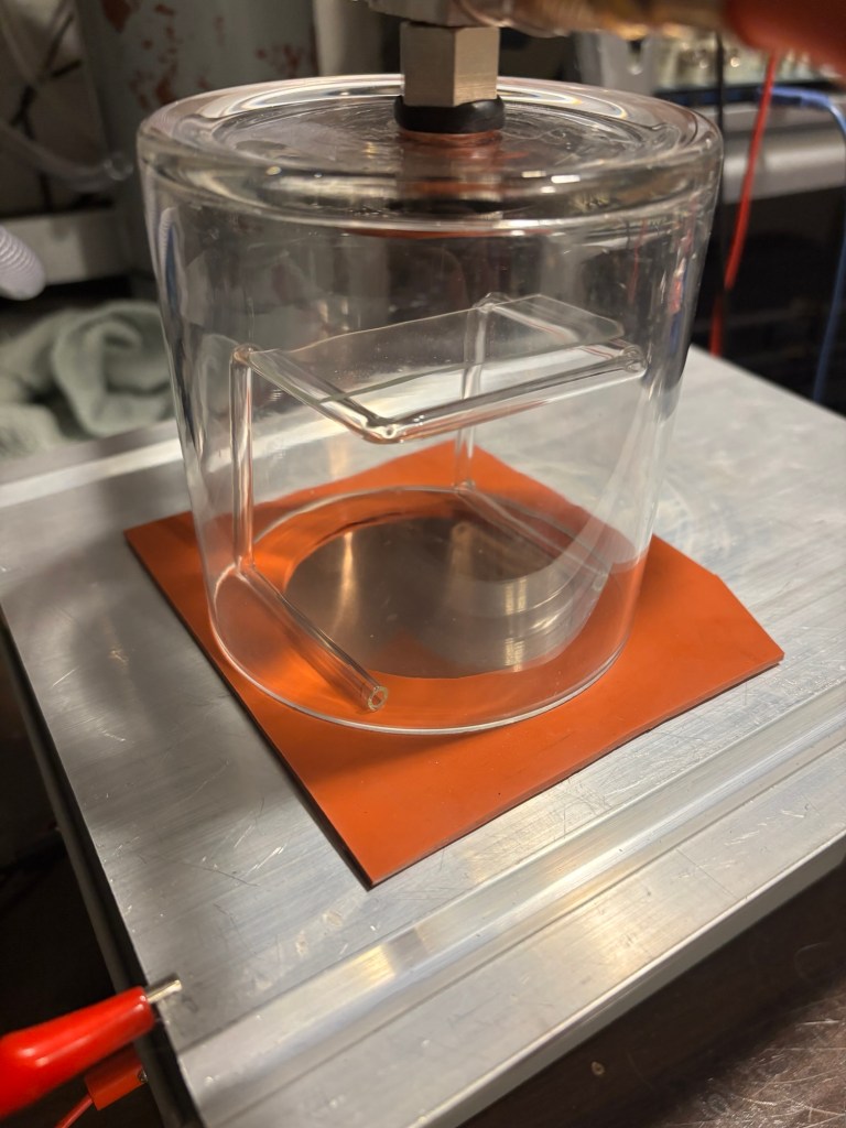
The magnetron was placed down on the heatsink.
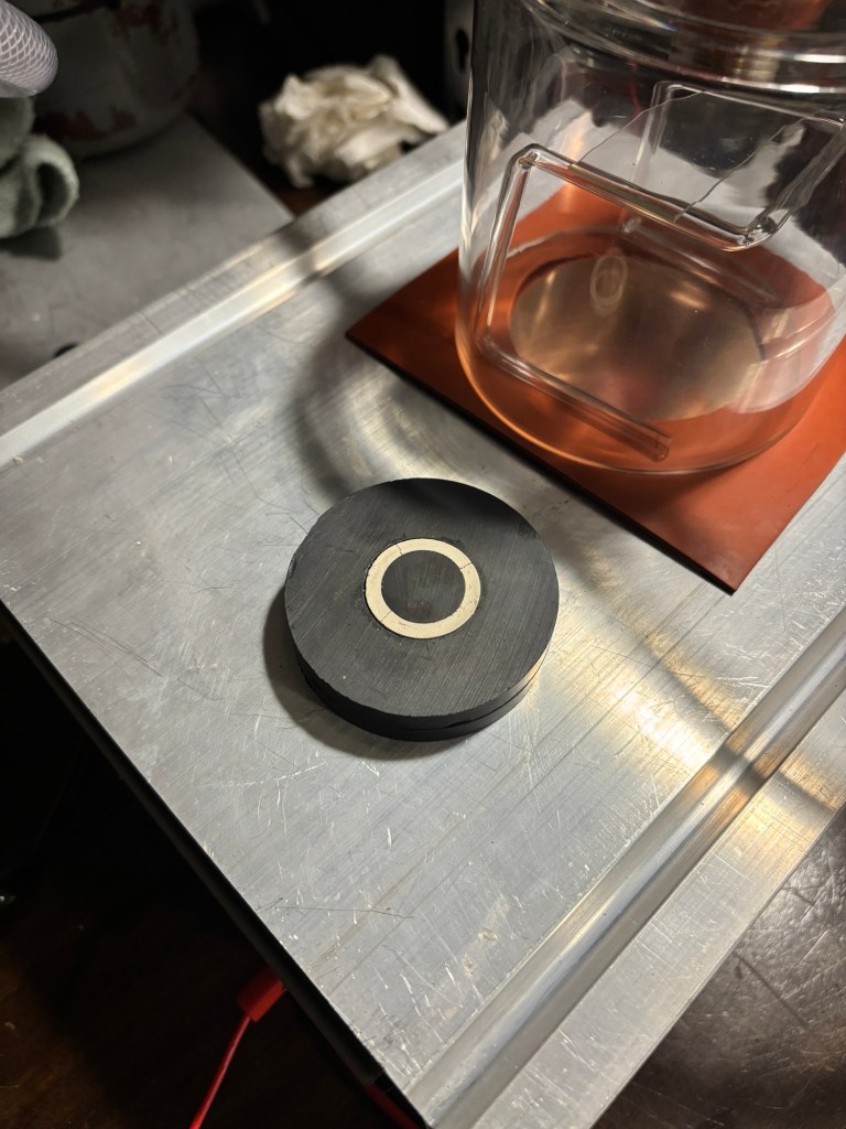
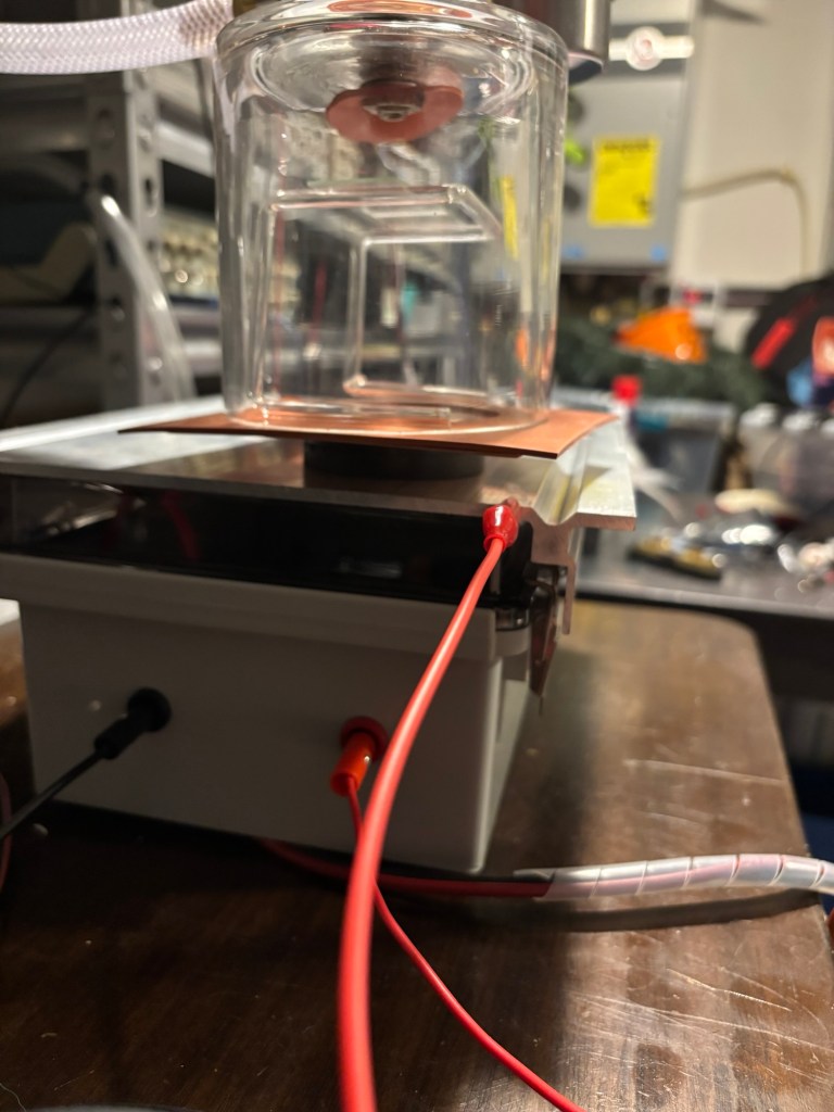
A vacuum was pulled on the jar, this kept the entire assembly stuck together which made it easy to place on top of the magnetron. Below the heatsink was the same flyback power supply used for the cold plasma needle. The only difference was I placed a microwave diode to half-rectify the output. The negative terminal was connected to the heatsink which is electrically connected to the magnetron and hence the copper target. The positive was connected to the brass vacuum feedthrough. I had to take care not to touch the system while high voltage was on.
A drawing of the assembly:
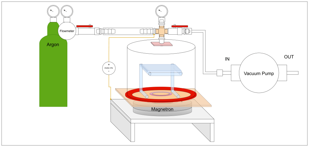
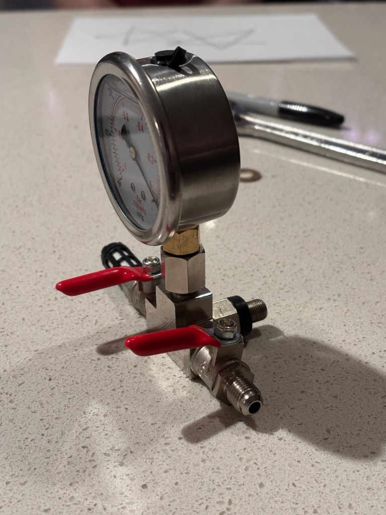
First a vacuum was pulled to get rid of the air, then the evacuated jar was closed off from the pump. Then the jar was partially filled with argon gas. Then the vacuum was pulled again by disconnecting the jar from the argon tank, then reconnecting it to the pump. Afterwards the HV supply was turned on and I would not touch the system until HV was turned off and discharge was proven.
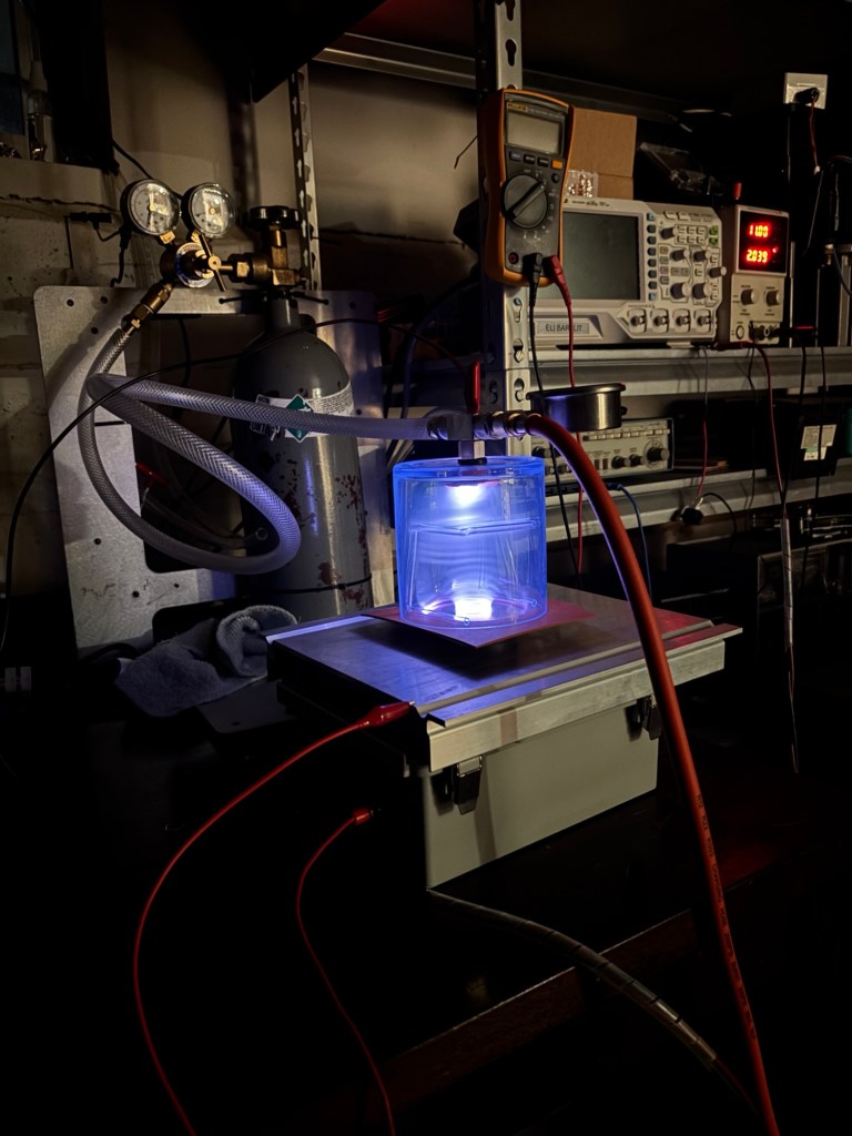
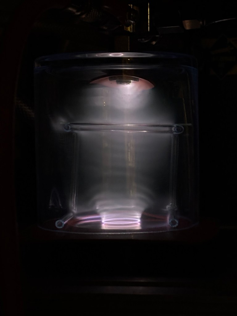
Failed attempts and playing around:
before adding diode. Breakdown to heatsink/cathode would bypass target completely in this configuration.
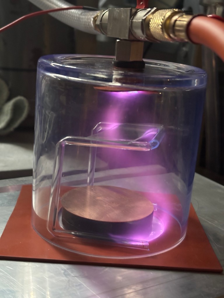
after adding diode. Lowered voltage to prevent breakdown seen above.
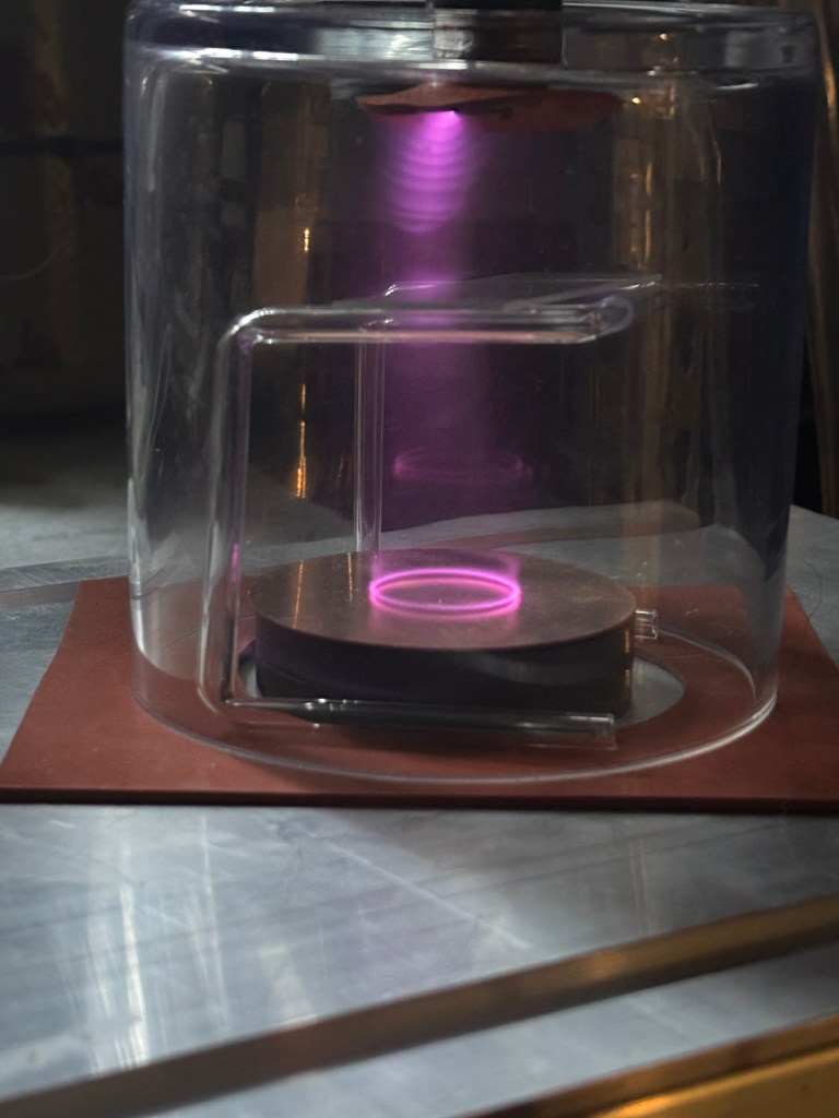
electron trap ring pattern on copper target
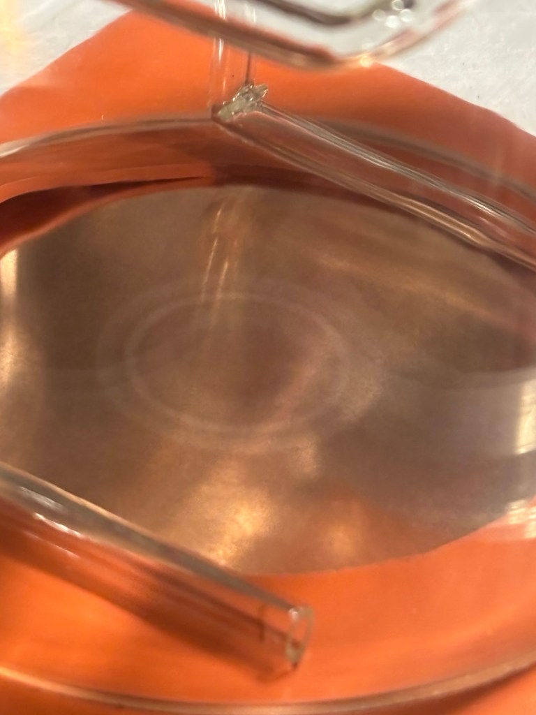
Issue: Too much oxygen and not enough argon
Playing with different configurations: Flyback transformer without diode
Fix:
Need to drill another hole specifically as an argon input, must be close to the magnetron/target. Replace argon hose with an airtight seal. The air hose I’ve been using has an internal wire mesh to prevent collapsing due to vacuum. unfortunately, it does not want to make an airtight seal due to this mesh. Need to replace.
SNS = face up magnetic polarity of magnetron is the outer ring being South and middle cylinder being North
NSN = “…” outer ring is North, cylinder is South
Red =
Black =
SNS: red top black bottom
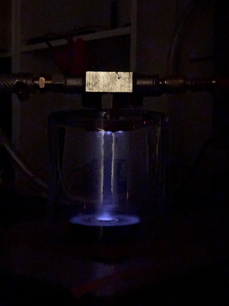
SNS: black top red bottom
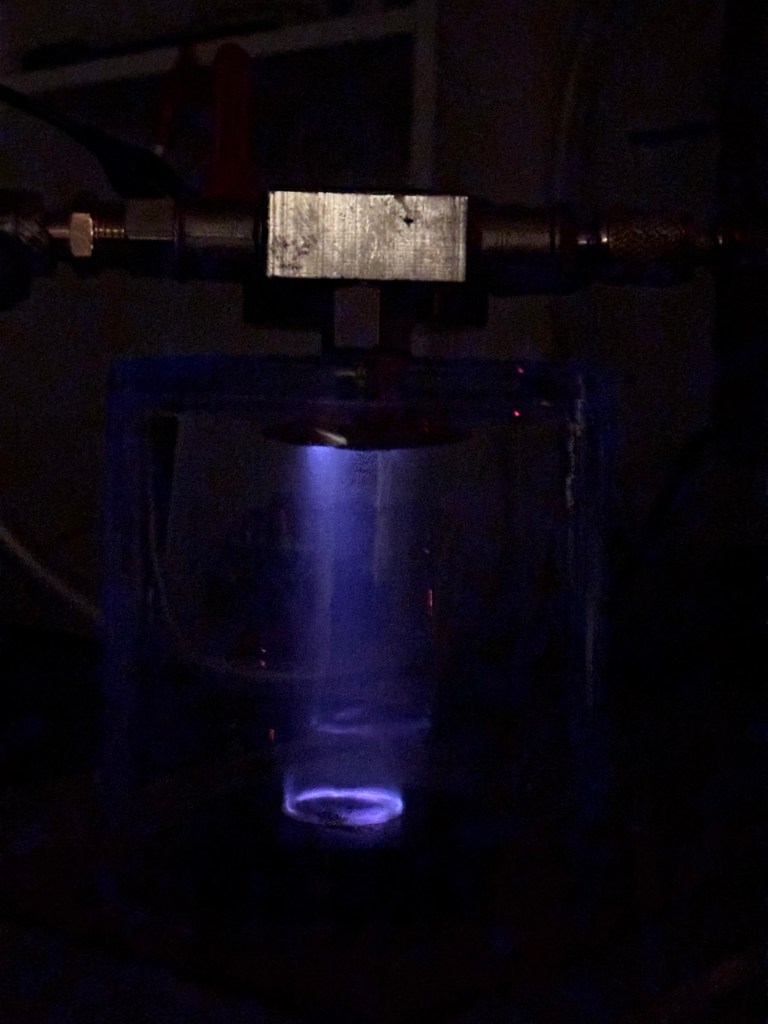
NSN:red top black bottom
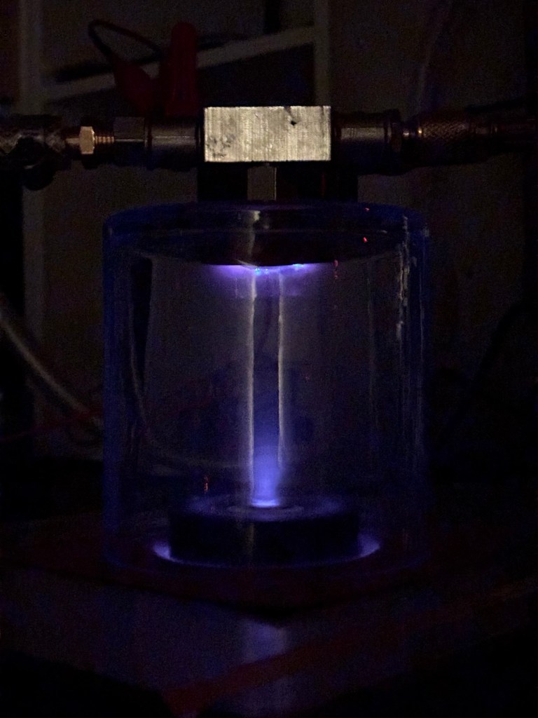
NSN:black top red bottom
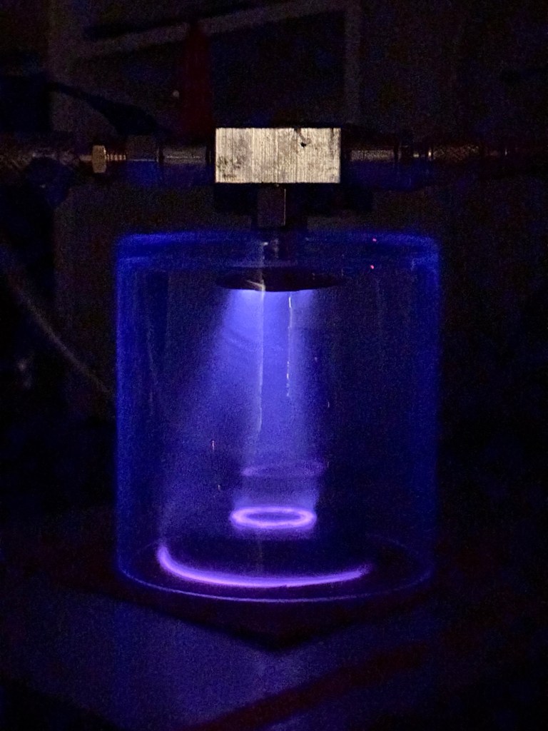
this plasma was driven by the ZVS-flyback circuit. A voltage divider
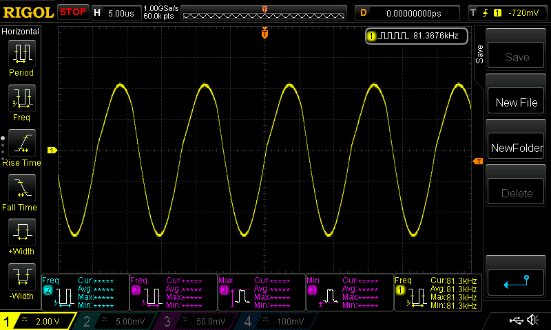
Second attempt
A couple problems to fix include increasing magnetic field strength, preventing oxygen gas from getting in, and increasing temperature of the target to help free more electrons. Increasing the power of the High voltage supply would achieve better heating. But the magnet would also get hot which needs to be better regulated
Improved magnetron:
- Ceramic magnet replaced with neodymium magnets
- Spacer made from Aluminum ring
- Magnetron sits in aluminum plate for better stability and heatsinking
- Heatsink added to bottom of magnetron
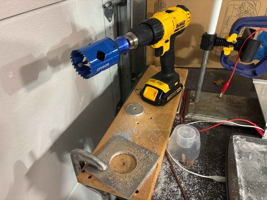
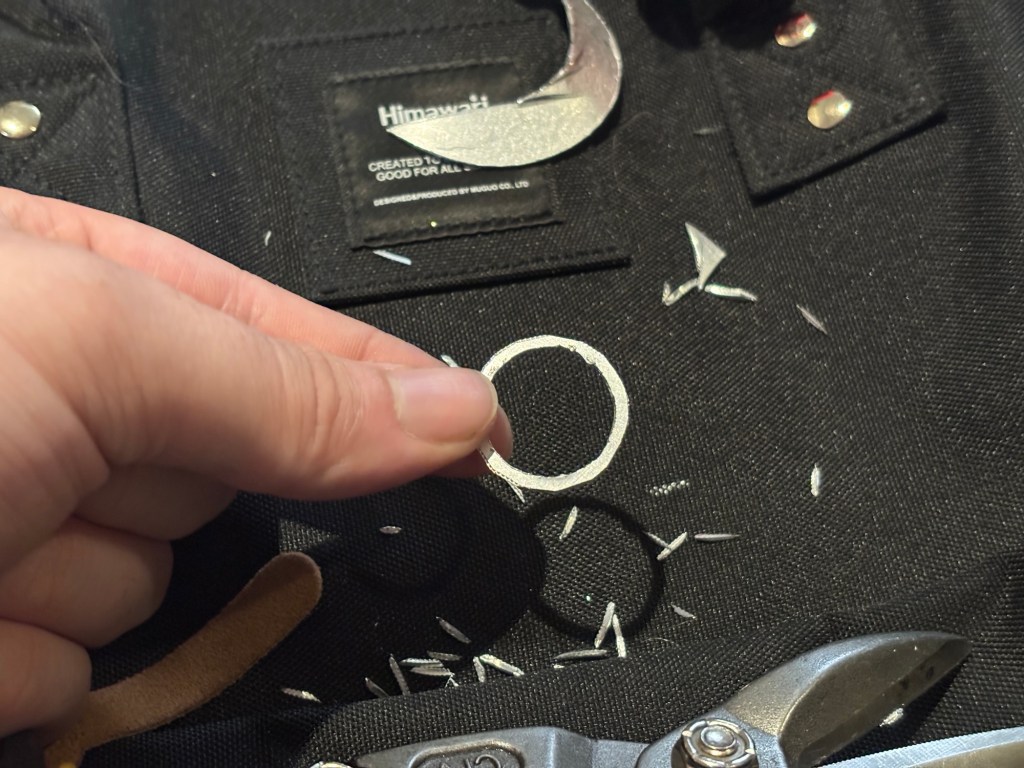

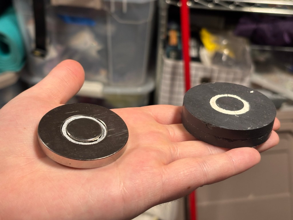
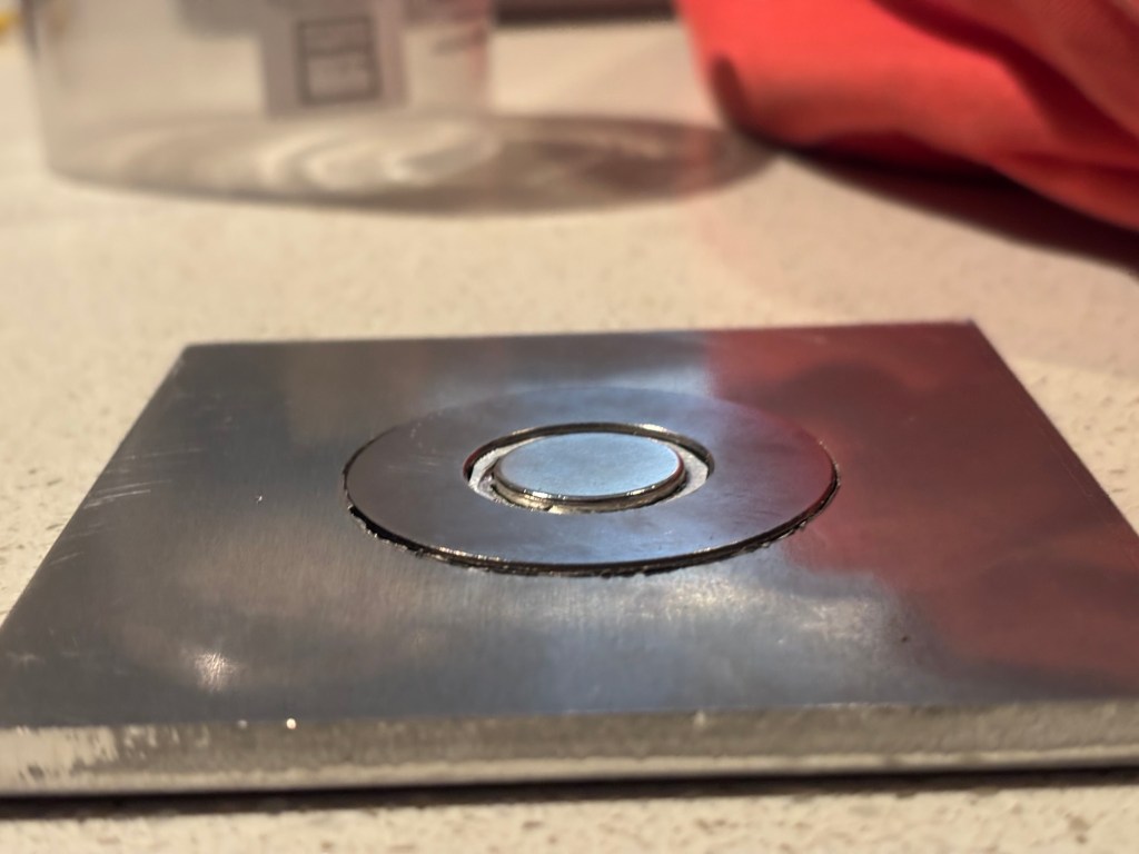
Change in HV Power supply
- Flyback transformer replaced with full-bridge rectified MOT to increase thermionic emisssions of electrons from high current alongside a more stable DC electric field to guide electrons to sample
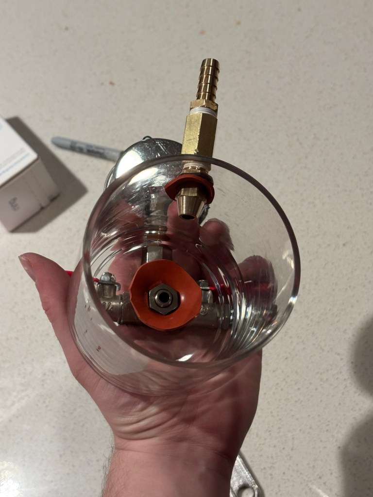
Separated the Argon inlet from the air outlet port
- Added another hole to allow continuous flow of argon gas into jar rather than evacuating then filling jar with low pressure argon gas.
 Eli Bartlit
Leave a comment