

Introduced by Erwin Otto Marx in 1925 for testing high voltage components and equipment (citation needed).
The Marx Generator (informally called a “Marx”) can be a simple way to boost high voltage DC into a higher voltage pulse with a large peak power.
Capacitors are charged in parallel through a high impedance and discharged in series, multiplying the voltage by the number of capacitor stages.
Process from transforming from a parallel circuit to a series circuit is known as “erecting the Marx”
A Marx generator includes energy storage, capacitors, and sometimes pulse forming networks or transmission lines, along with a switch. It’s important to carefully assess how over-voltage affects the switches.
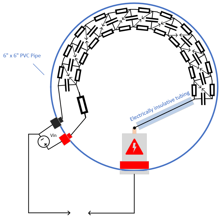
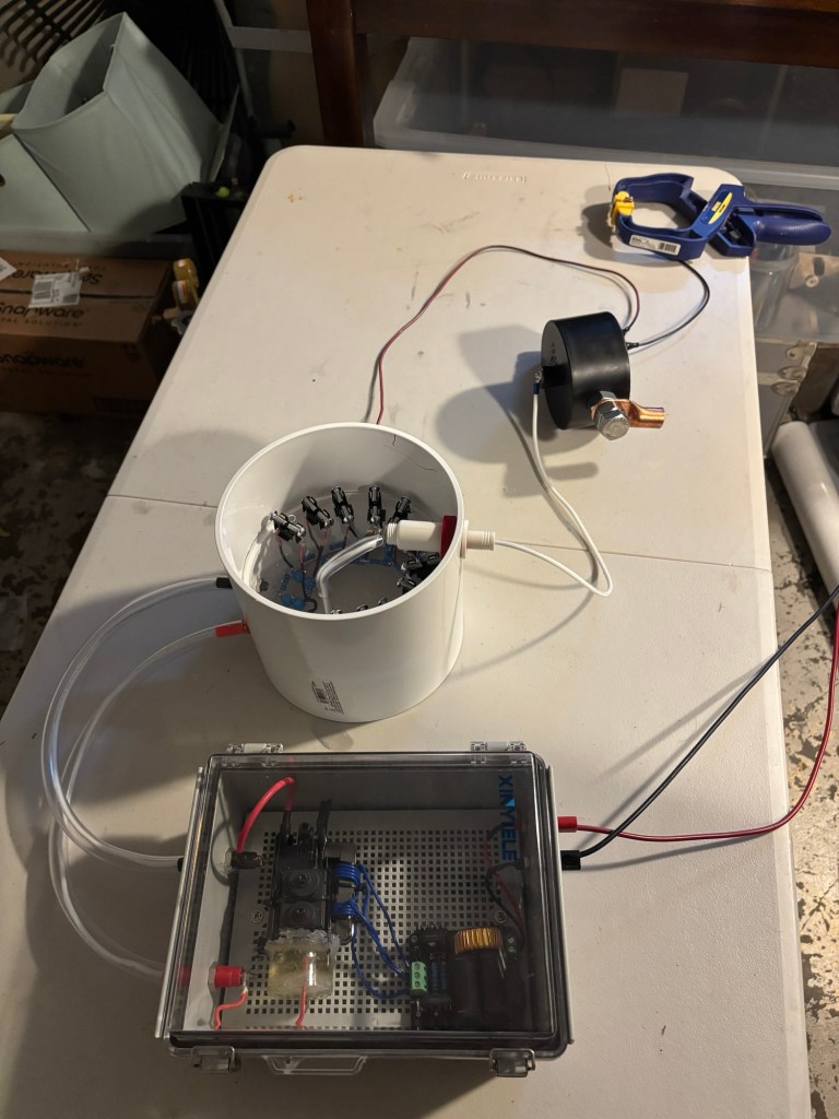
The input voltage is from a ZVS-flyback transformer
The resistors are all 1Mohm, 2W, 1% metal film resistors
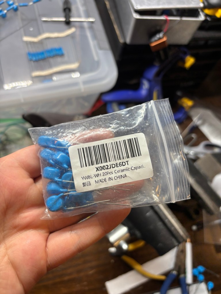
the capacitors are 20kV, 1nF
Each stage-capacitor consisted of two 1nF capacitors connected in series, resulting in an equivalent capacitance of 0.5nF per stage but also doubling their voltage rating to 40kV.
The output capacitance is therefore (Nstages)(Ceachstage) = 10(0.5F) = 5nF
Parts list
Marx Generator
- 20kV 1nF Ceramic Capacitors (20x)
- 2W 1M ohm 1% resistors (23x)
HV Power Supply
- ZVS driver + flyback transformer (1x each)
Basic Theory
When you think of a component that stores energy, you should think of a capacitor (I’m going to assume you know what capacitors are).
If you have a number N of capacitors in parallel, they will all charge up to the same voltage when connected to a DC source.
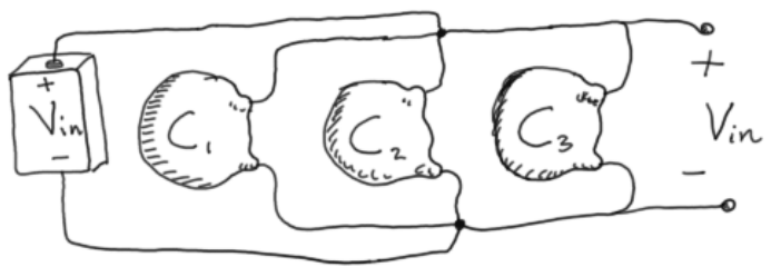
Once they are all charged, re-arrange them in series. The voltage between the top-most capacitor plate and bottom-most capacitor plate will be the sum of all the individual voltages. So the open output voltage Vout = N(Vin).
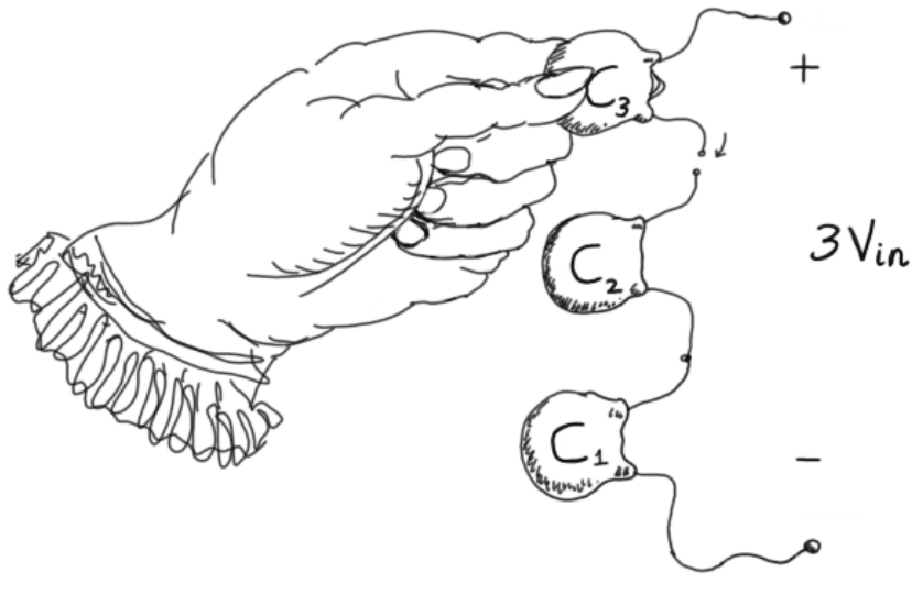
*Consider how a couple of 1.5V AA batteries connected in series will give you 3V. This is similar while all the capacitors remain charged.
Handling charged capacitors is dangerous and inconvenient. You should use switches.
Charging the Marx
When the capacitors are charging, you CLOSE all the switches that connect the capacitors in parallel, but OPEN all the switches that connect the capacitors in series.
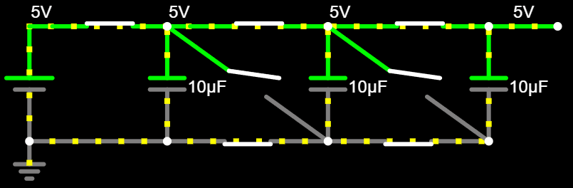
Erecting the Marx
Then when all the capacitors are charged, you now do the inverse and OPEN the parallel switches and CLOSE the series switches. The process of changing from Parallel connections to series connections is called “Erecting” the Marx.
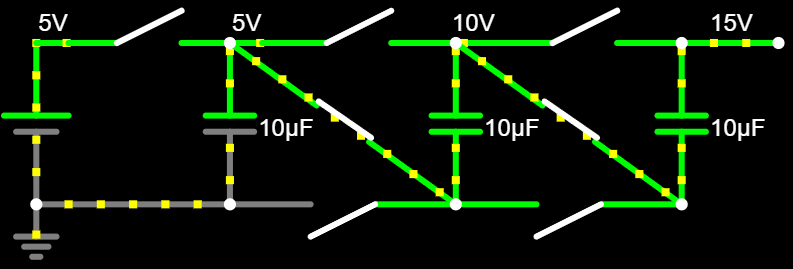
Notice how each capacitor sees a higher voltage than the last one going from left to right.
Replace Parallel Switches with Resistors
The function of the parallel switches was to allow for capacitors to charge, then isolate during discharging/firing. However, I only did this to simplify the most basic mechanism of how a Marx generator works.
These parallel switches won’t get you very far.
Instead, use resistors as they have many benefits:
Function of Resistors during charging phase:
- Offer a pathway to charge capacitors
- limit charging current to prevent burning out the capacitors
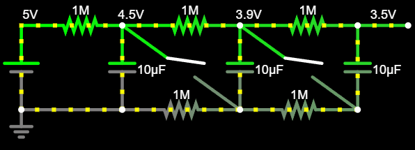
Role of Resistors during Erection phase:
- Makes the parallel connections are high impedance. The series configuration is the path of least resistance during erection (if the resistance was low, you would just short out the power supply).
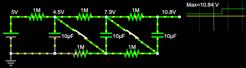
Replace the Series Switches with Spark Gaps
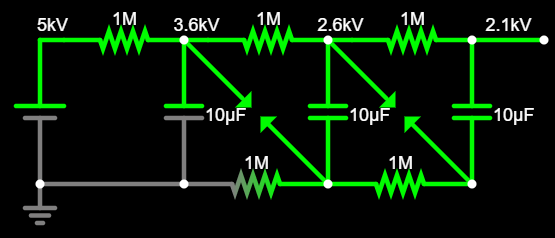
until we move the output end close enough to the load. small capacitance between the output wire and output load requires that current goes through the spark gaps
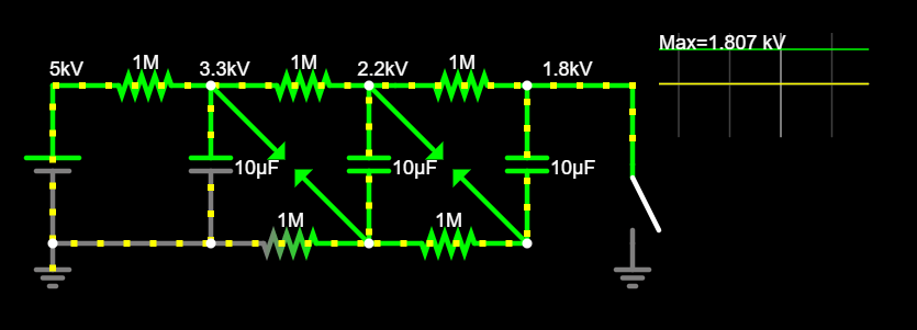
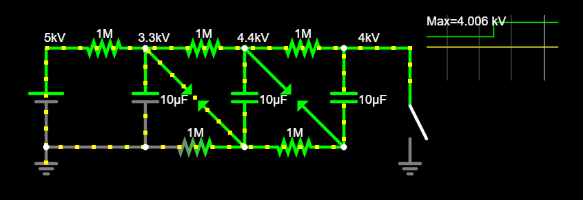
Instead, we can use spark-gaps in place of the series switches. Adjust their distance so they breakdown when the capacitor voltage is close to fully charged.
Now for the Parallel switches. You could replace them with resistors
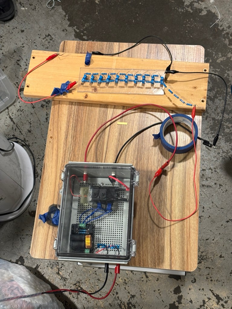
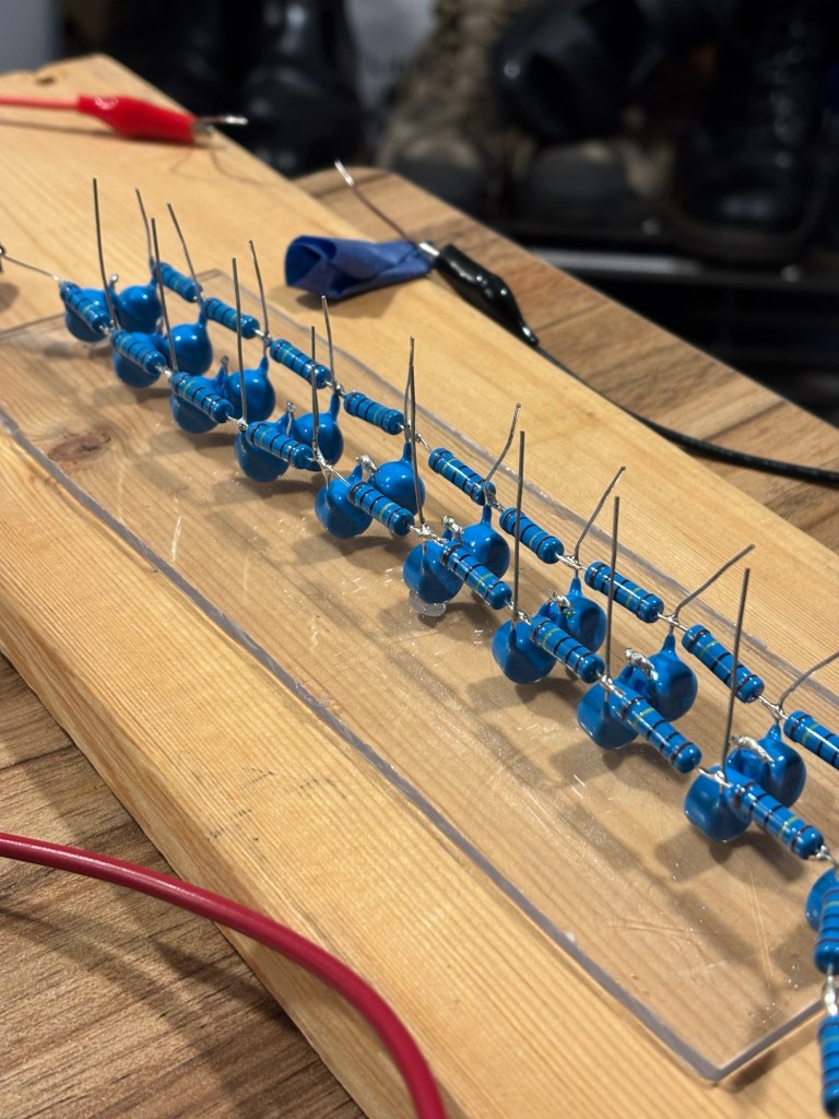
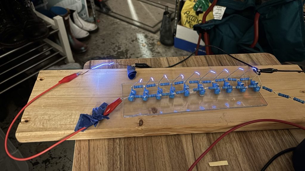
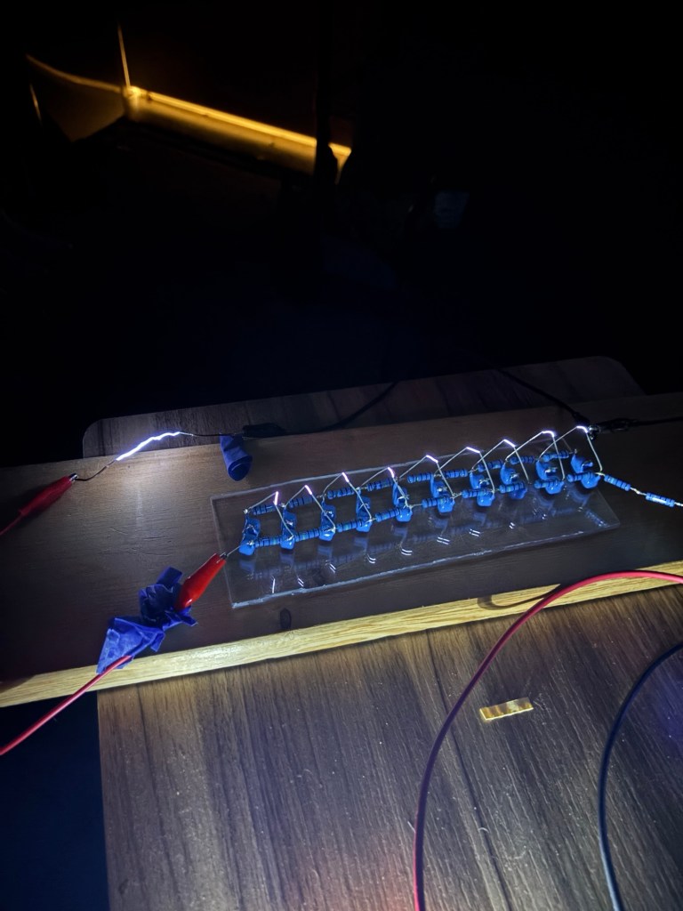
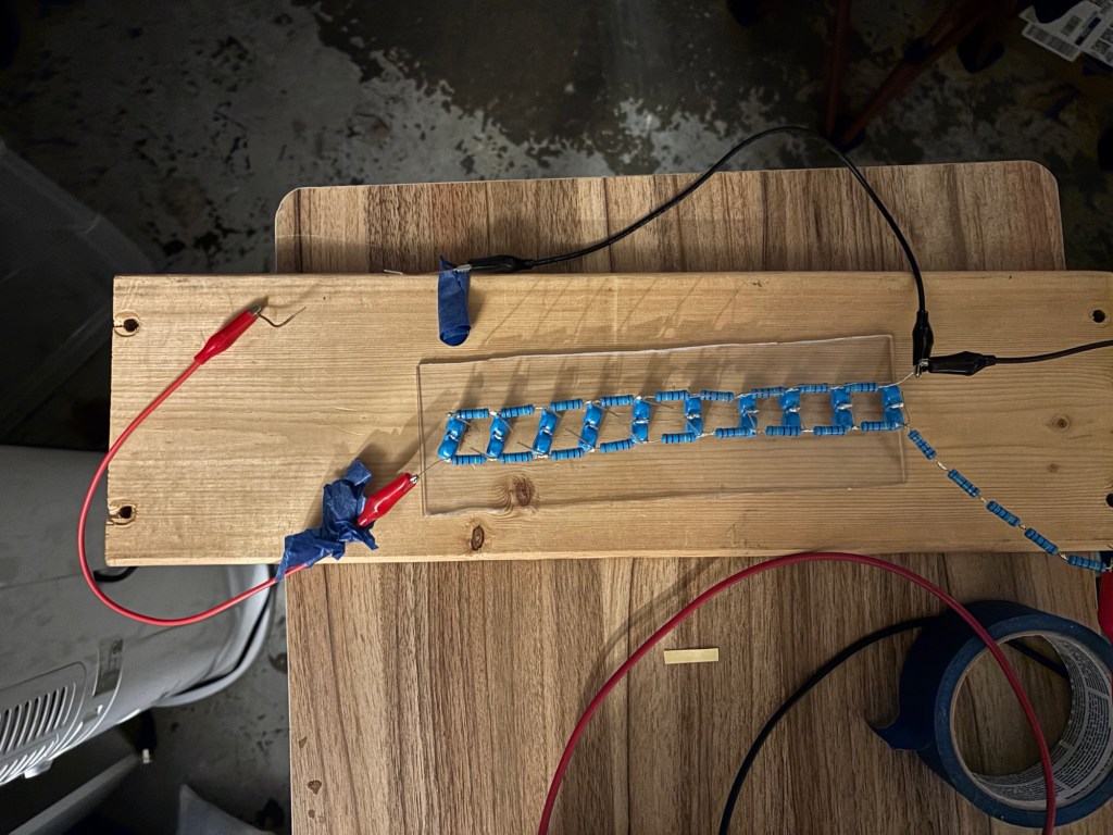
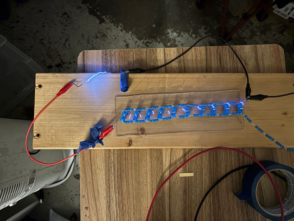
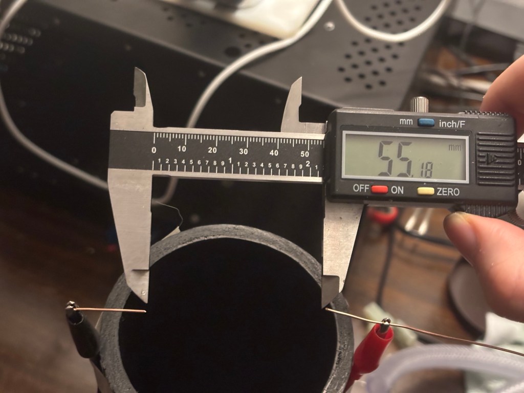
The rule of thumb for the dielectric holdoff of air at sea-level is ~3kV/mm. A spark gap of 55mm gives us around 165kV output. For a more accurate estimate I would need to factor in electrode shape, temperature, humidity, pressure, and composition of gas.
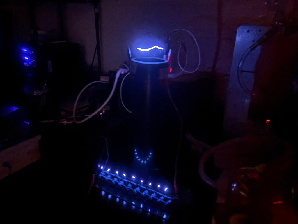
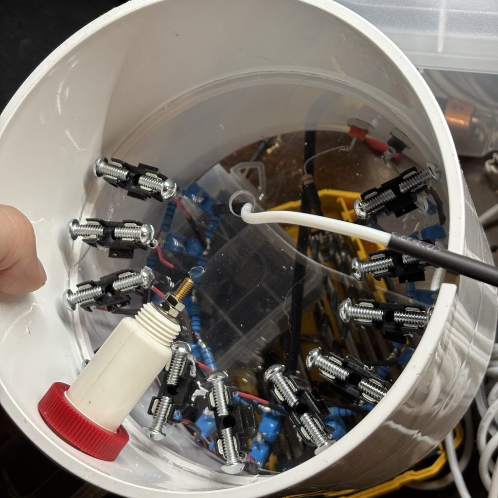
Marx 2.0: cylindrical housing and adjustable spark gaps
For a more appealing shape and adjustable/replaceable spark-gaps
Diagram:
Parts list
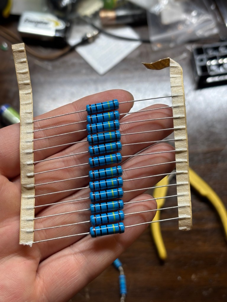
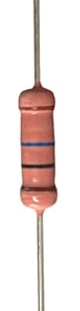
2W 1M ohm 1% resistors (22x)
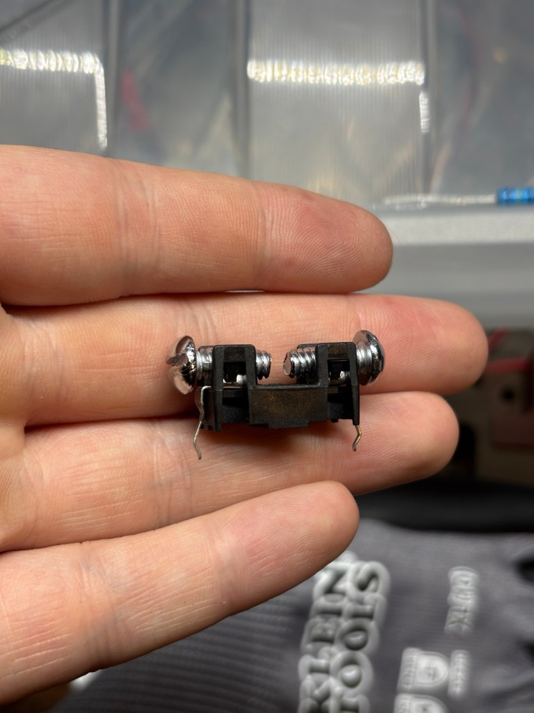
10-24 x 1/2 bolts (22x)
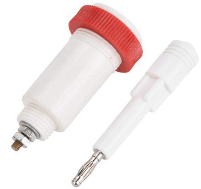
10kV 4mm Banana Jack (1x)
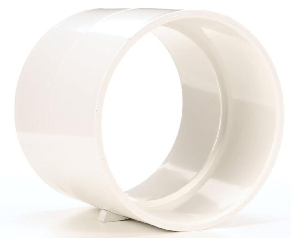
6″x 6″ PVC Coupler (1x)
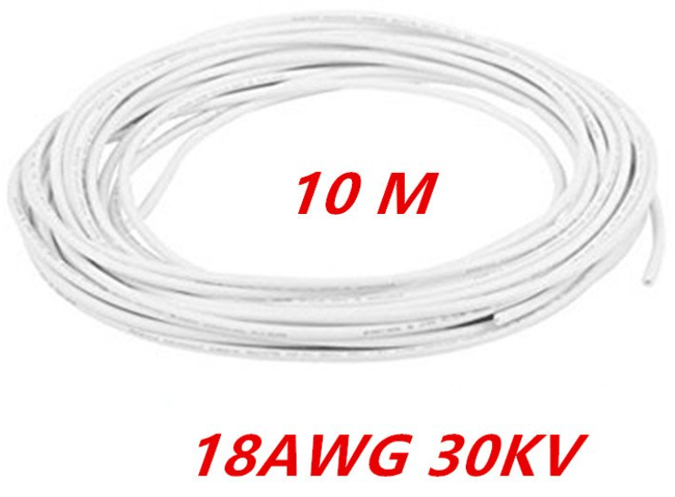
Assembly
Marx Generator:
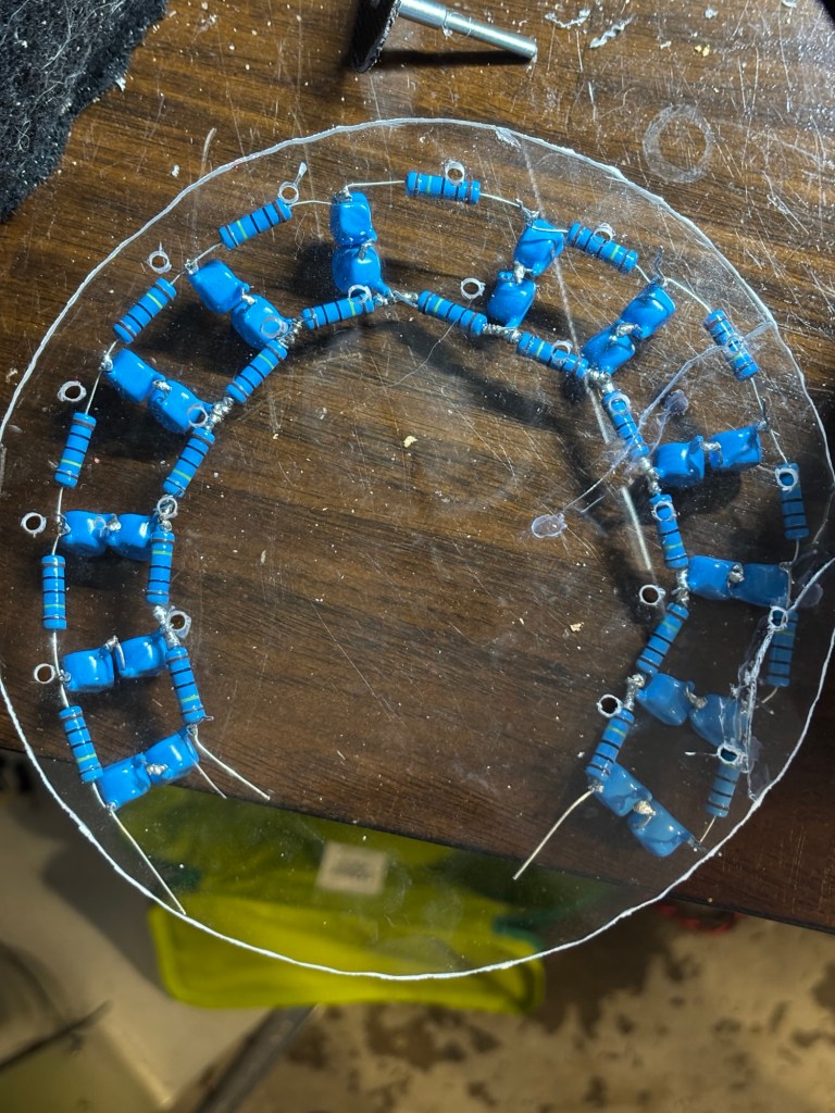
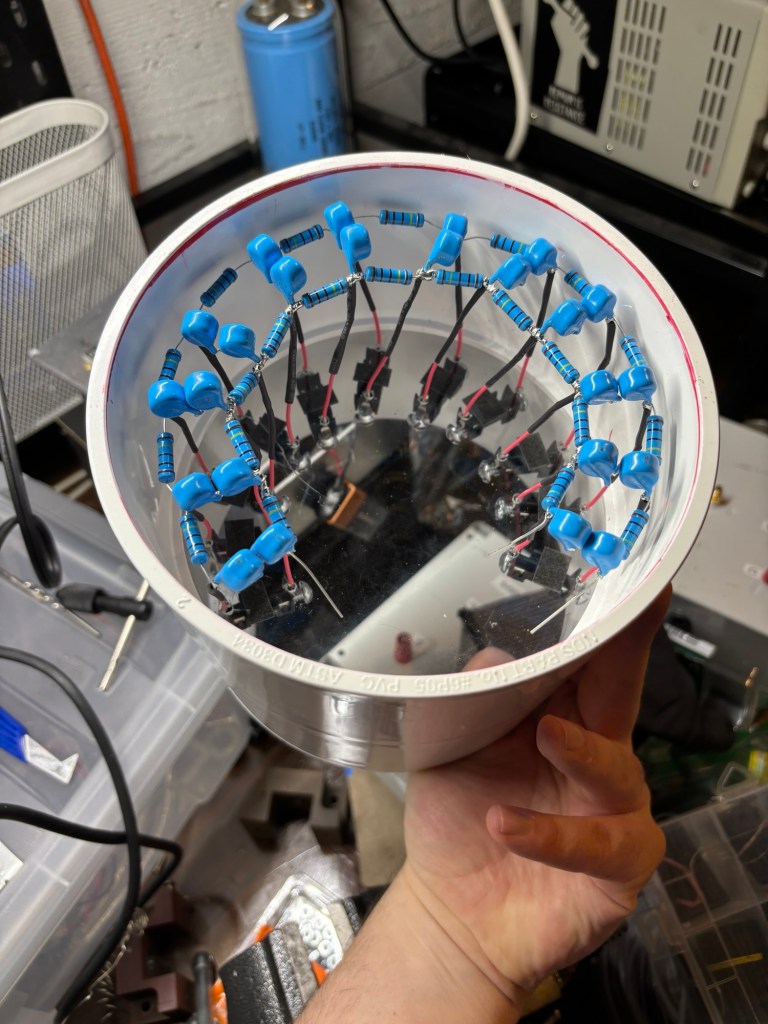
I decided to build a 12-stage ladder type Marx as it was the highest amount of stages I felt could be fit into a cylindrical disk shape in atmosphere without unwanted arcing given the components at hand at the time.
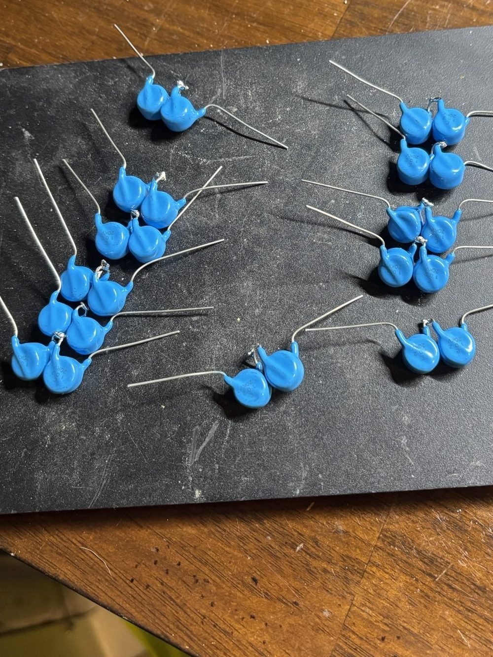
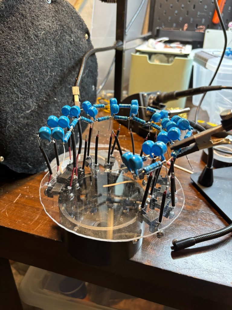
I started by soldering two 20kV 1nF caps together for an equivalent of 40kV 0.5nF. Then made a total of 12 equivalent caps
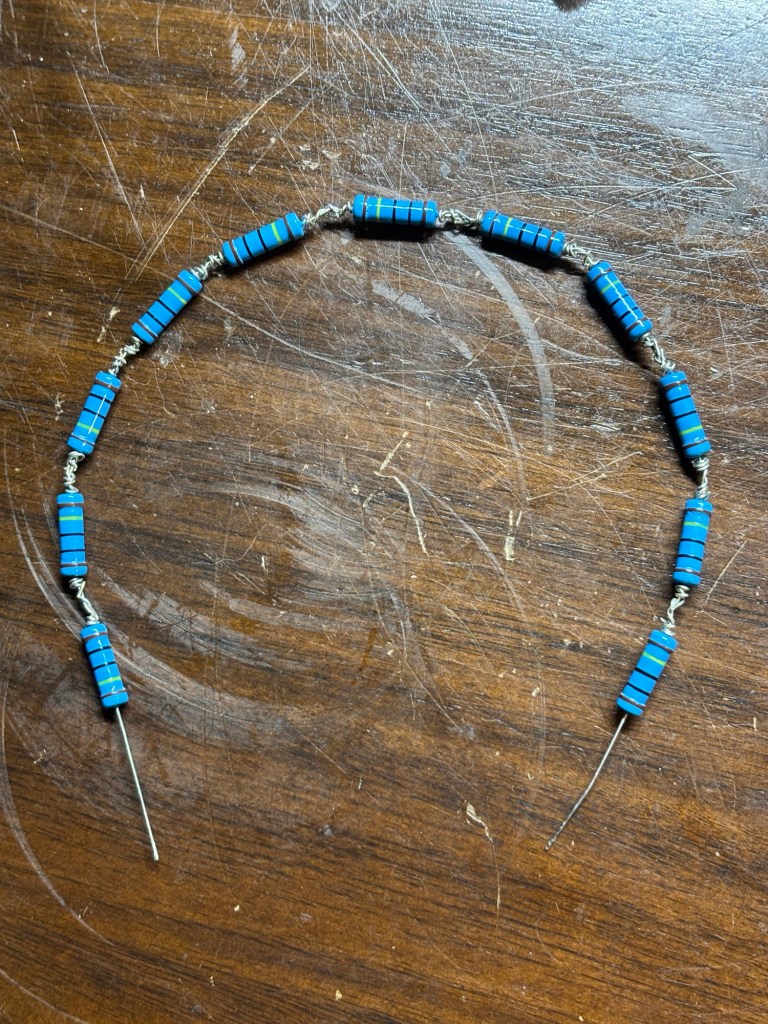
Then Soldered together an inner ring of resistors
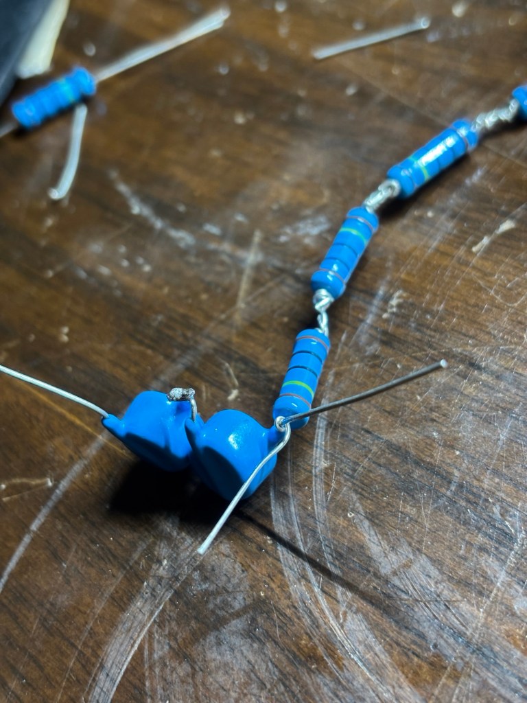
I would then twist the leads around each metal section of the ring.
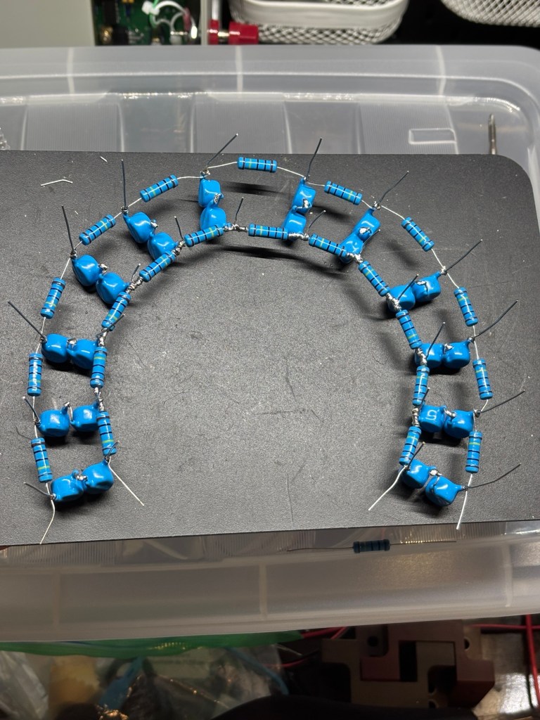
Then solder on a longer outer ring. Ensuring it would fit within a 6″ diameter tube.
Adjustable Spark Gaps:
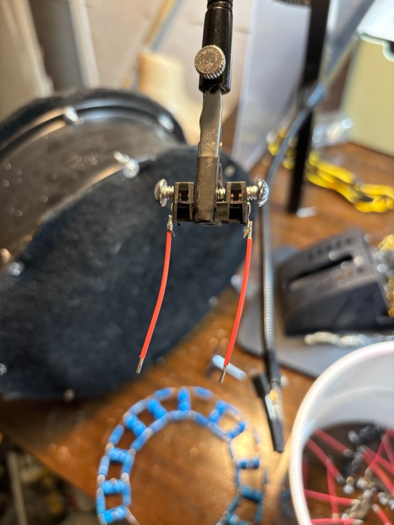
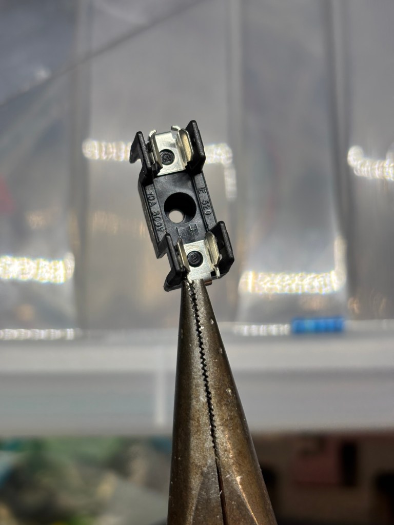
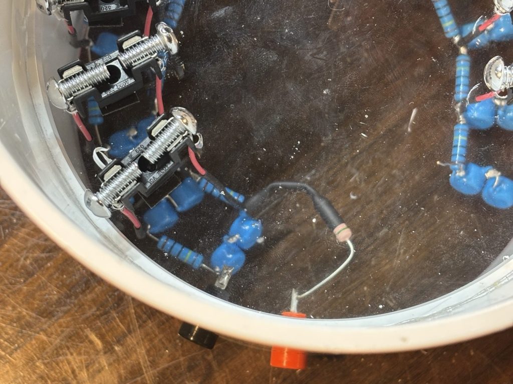
Pressing some screws into the fuse holder and soldered on some leads will serve as an adjustable spark gap.
Using a steel guitar string and my bench-top power supply, I cut out an acrylic disk that would fit on the lip of the middle of the PVC pipe (make sure you’re in a well ventilated area if you do this).
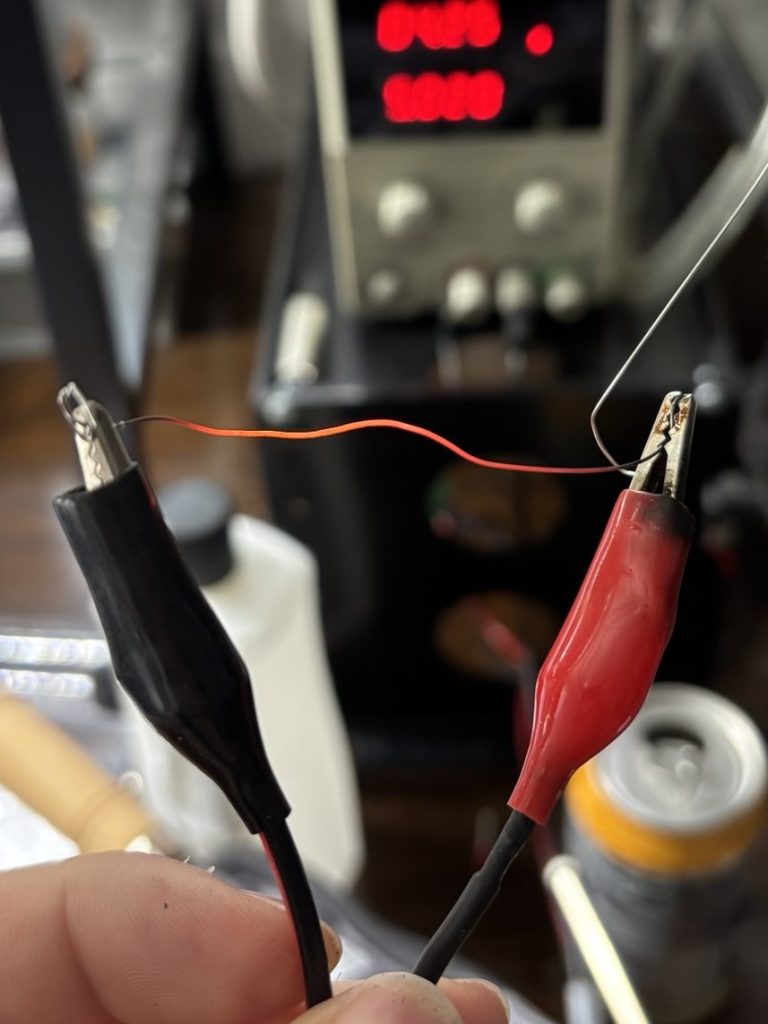
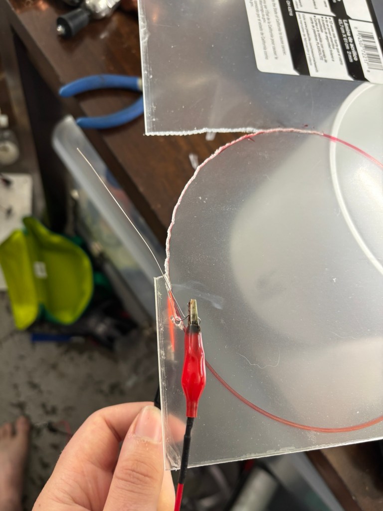
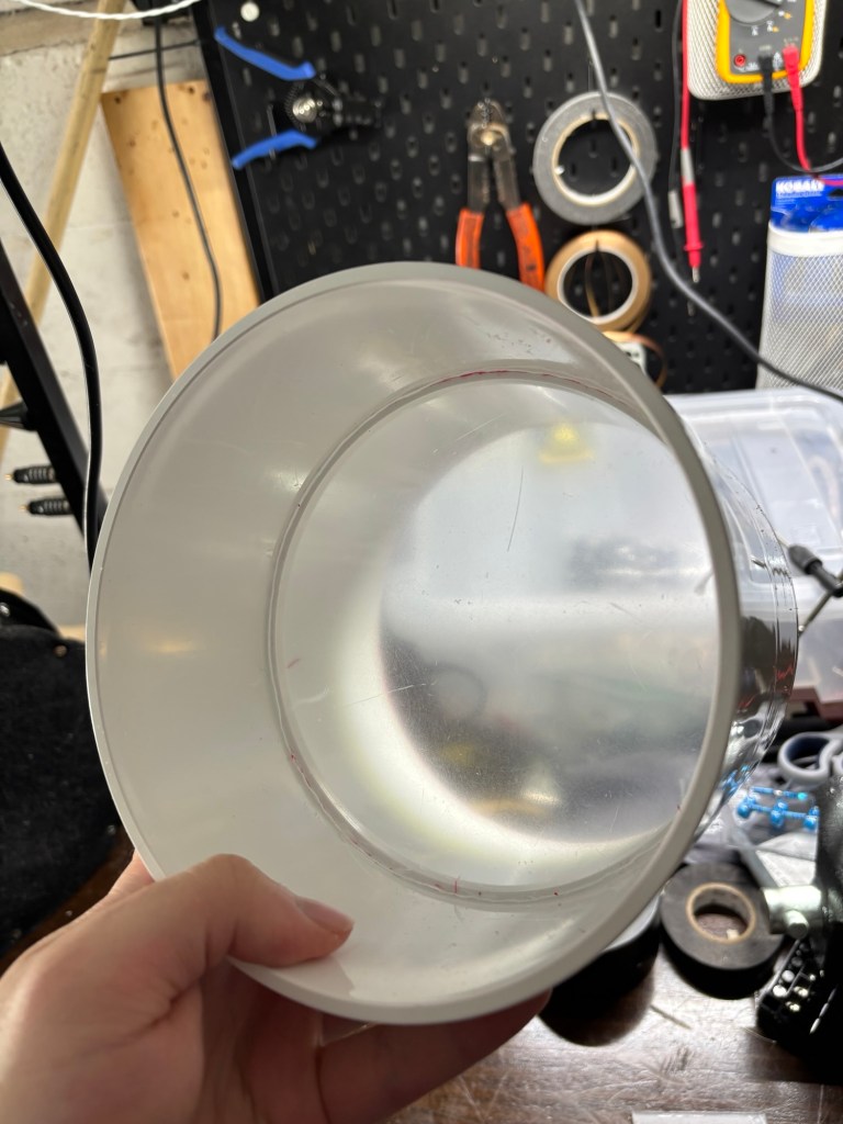
holes drilled for feeding through the spark gaps.
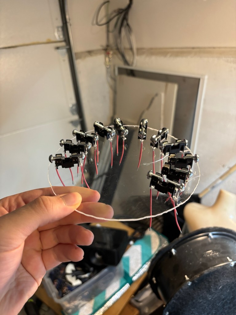
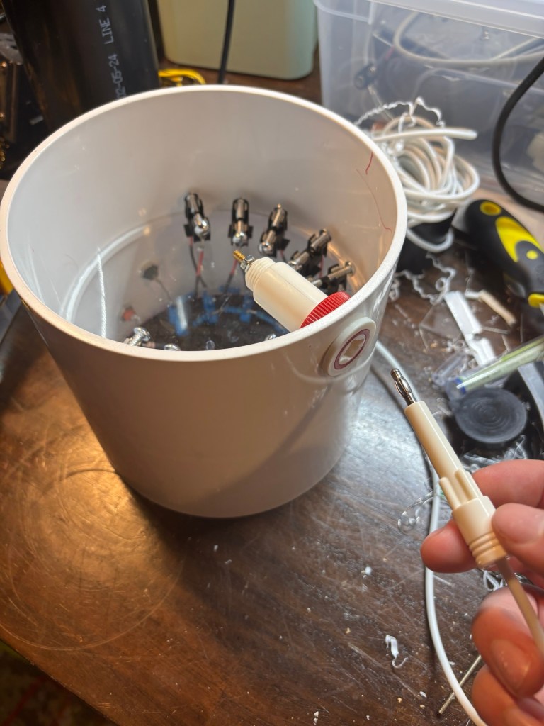
Input/Output banana Jacks
Test
first test
2nd test – Higher Input voltage, Marx turned onto it’s side for better view of spark gaps
 Eli Bartlit
Leave a comment