

Simple automation without a microcontroller
We have an AC unit setup so the condensed water from the dehumidifier can flow down a tube and into a bucket.
I forget to check the bucket, the water overflows into the pan I placed under the bucket…because I knew I would forget.
Me and a coworker had a common problem. My coworker used an Arduino to sense when the bucket was full.
I want to try using comparators.
The Comparator
The following drawing shows an operational amplifier (aka op amp):
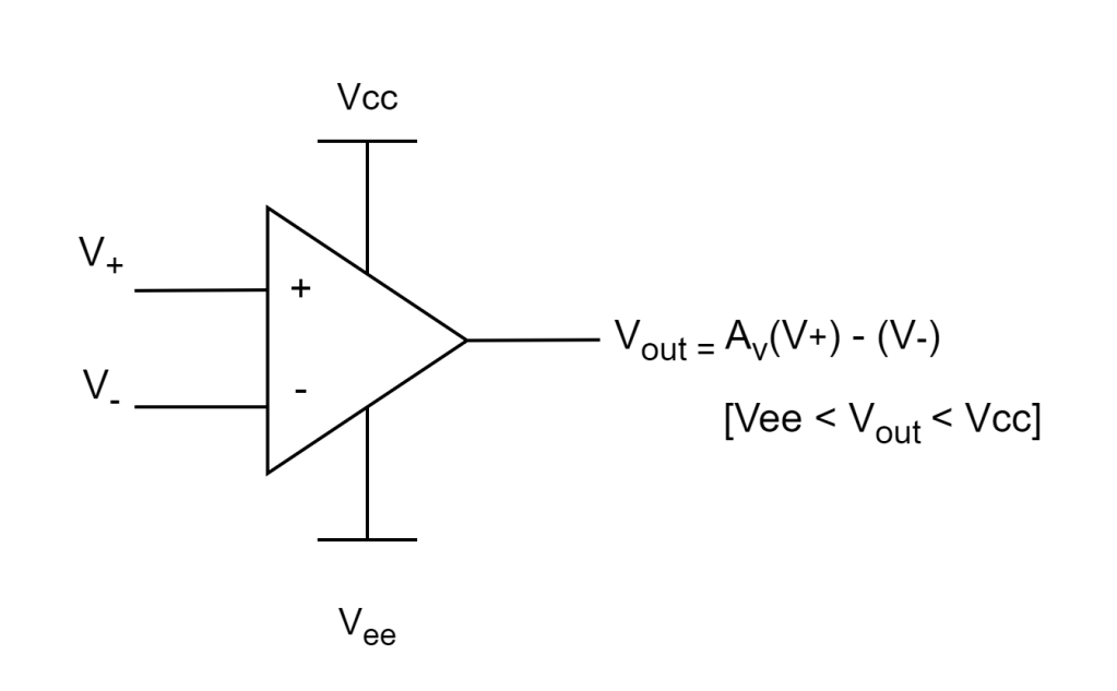
The basic characteristics of this component are below:
- The inputs (V+ & V-) have high impedance, minimally affecting the connected circuit.
- Different voltages can be applied to the inputs without needing to be equal.
- An op-amp has a very high open-loop gain (Av = thousands range).
- Due to the large Av, when one input is higher than the other, the output will rail to either its maximum (Vcc) or minimum (Vee) value. This is also called a comparator circuit.
Example:
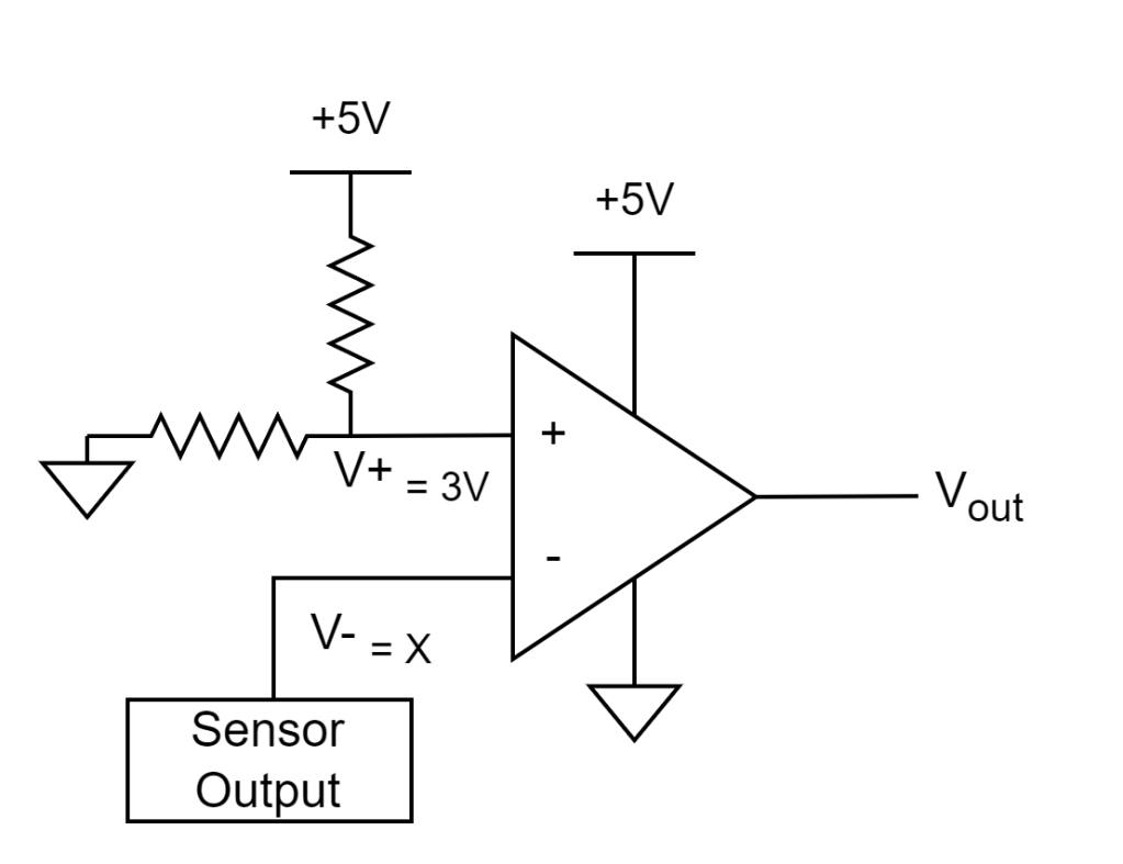
An op amp has been configured to the following comparator circuit:

I connect the op amp to a simple 5V supply and pick the resistors of the voltage divider so that the output V+ is 3V. Now we have the following circuit:
- Vee = 0v (ground)
- Vcc = 5V
- V- = variable voltage output from moisture sensor
- V+ = 3V
Here’s the output equation
Vout = Av( (V+) – (V-) )
Assume the open gain Av = 5000 (datasheet)
Vout = 5000( (V+) – (V-) )
And we know V+ = 3V
Vout = 5000( (3V) – (V-) )
*And remember Vout cannot go higher than 5V or lower than 0V
So this means…
Vout = +5V when the sensor output V- is less than 3V. Otherwise Vout = 0V
Now let’s flip the inverting and noninverting inputs.
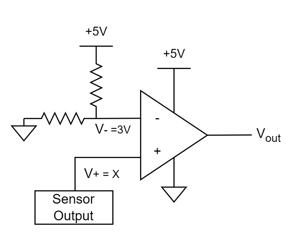
Vout = Av( (V+) – (V-) )
So if we set V- = 3V
Vout = 5000( (V+) – (3V) )
Which means…
Vout = +5V when the sensor output V- is more than 3V. Otherwise Vout = 0V
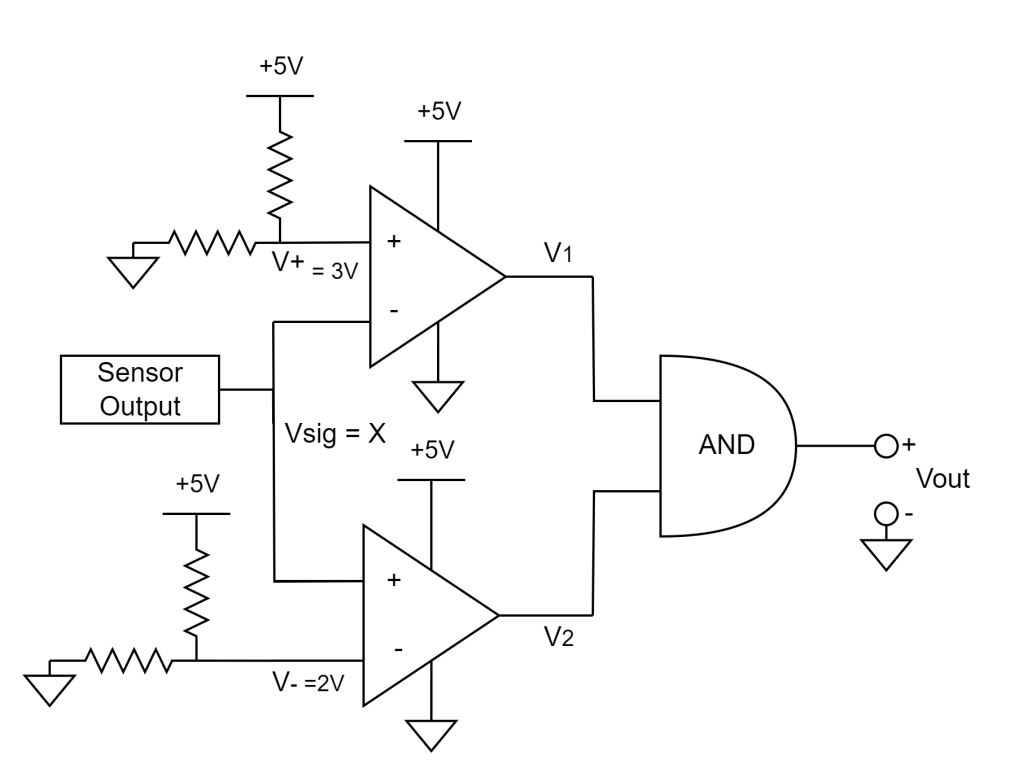
Window Comparator
Combine the the above two comparators together, so they share the same sensor signal.
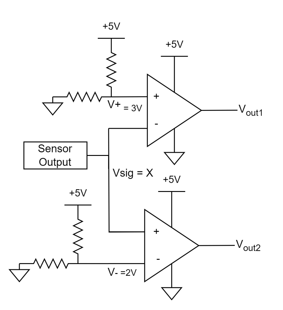

Now let’s feed the two comparator outputs into an AND gate.

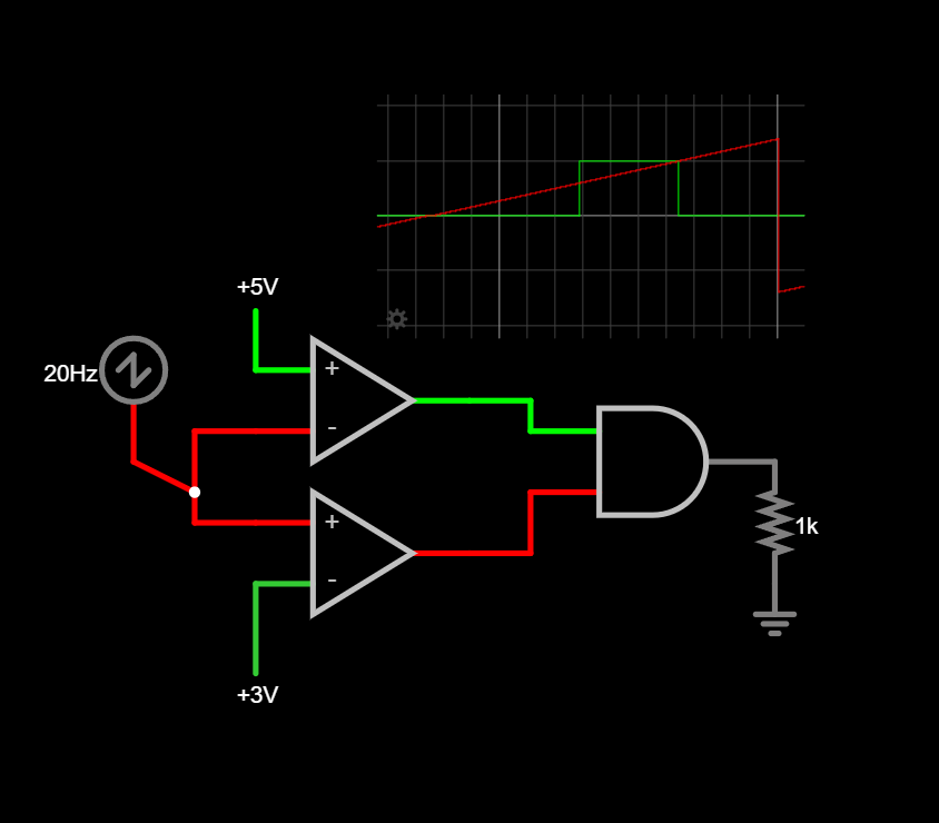
falstad simulation:
Red plot is Vin as you steadily increase the voltage
Red plot is Vout which is high only when Vin is between 3 and 5V
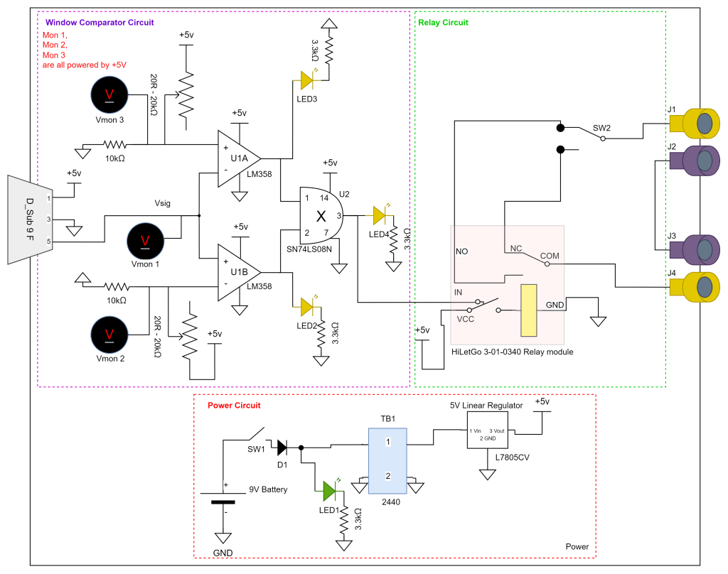
Window Comparator Relay Controller
We can now have our window comparator output control a relay module that takes care of isolating our window comparator from any pesky flyback from switching the coil on and off.
Making the voltage dividers adjustable with potentiometer dials allows us to change our reference voltages and calibrate for specific signal voltages! This means I can use almost any sensor that outputs a DC signal.
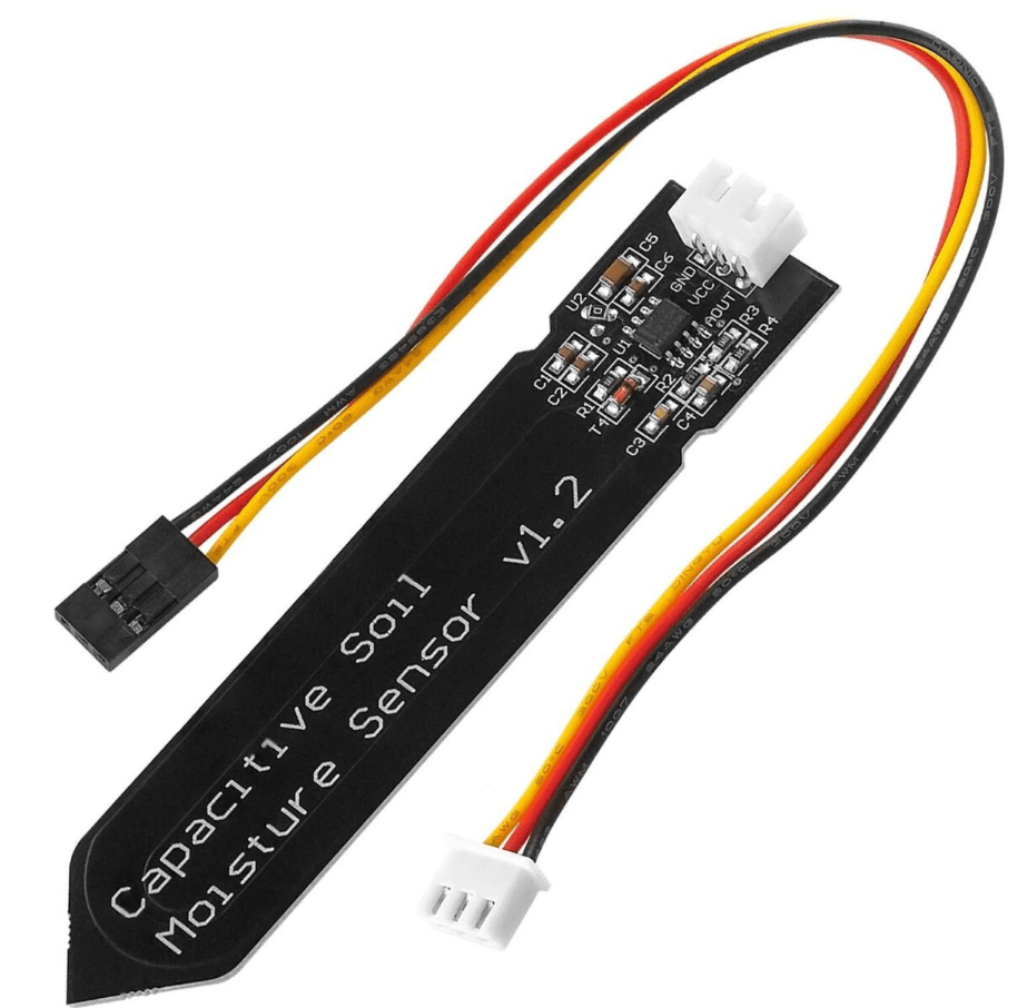
A simple method to detect water is by using two exposed wires hanging above the waterline. When the water reaches the wires, it lets electricity flow between them, which closes a switch. However, this can cause electrolysis, leading to wire oxidation. Gross
So I will use a capacitive moisture sensor as the metal never makes physical contact with the water.
The Window comparator circuit will be made using LM358N Op amps as I already had some lying around.
The LM358N pinout info:
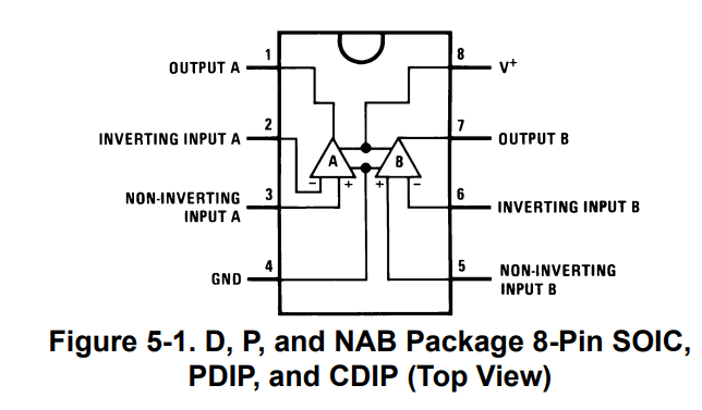
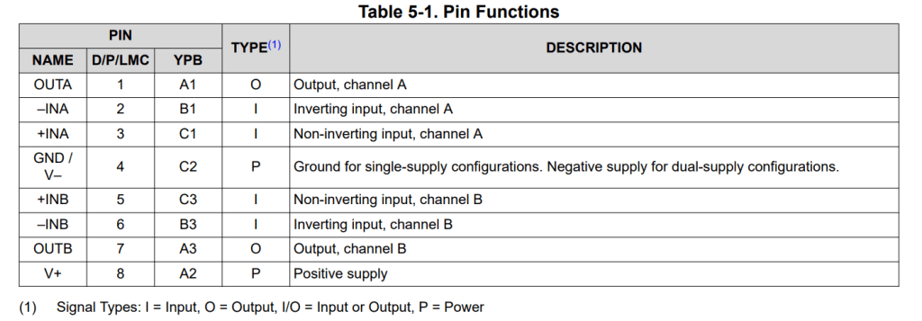
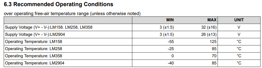
datasheet I pulled these figures from can be found here
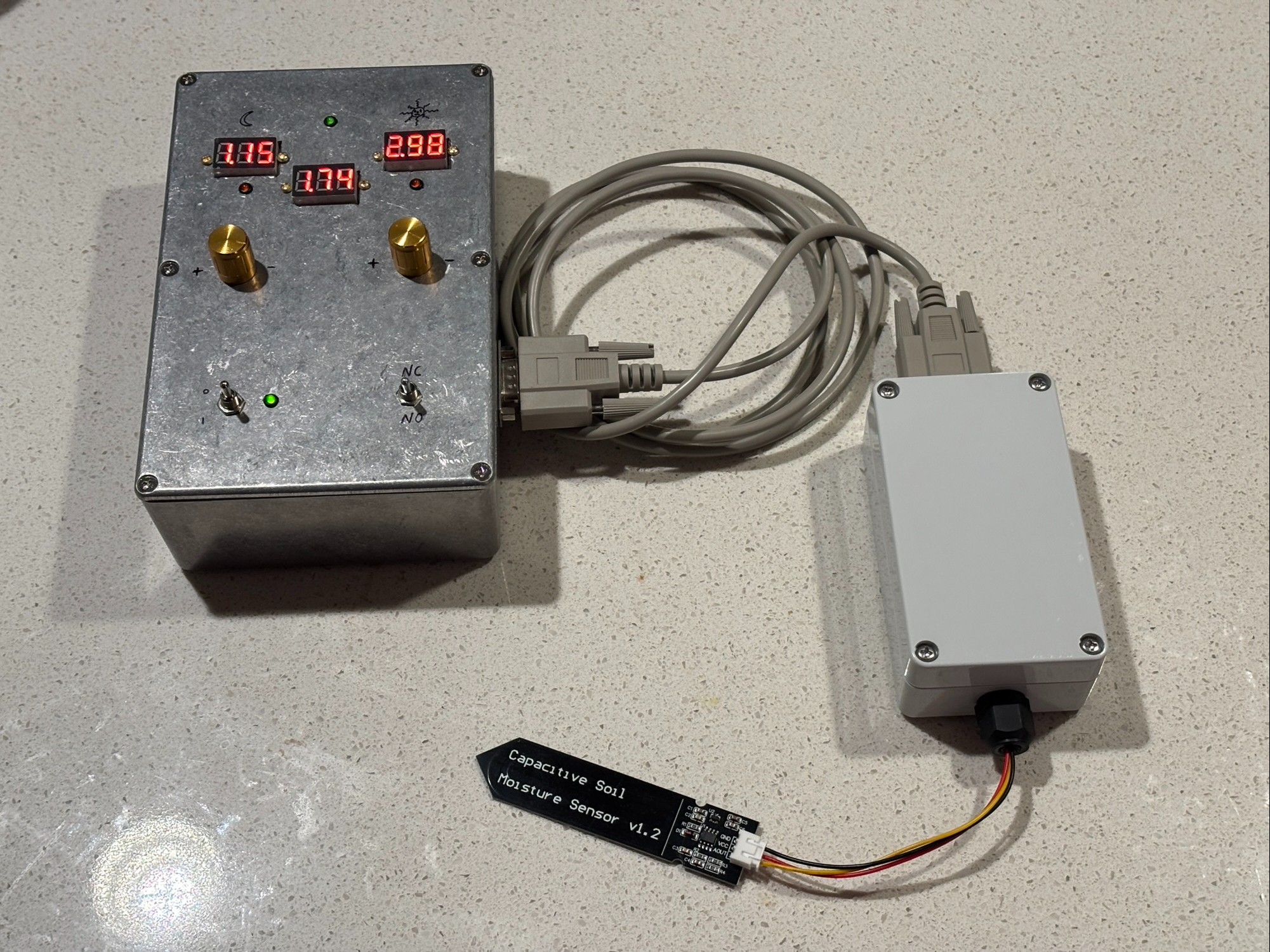
First Prototype
LED’s indicate when the inputs/outputs of the AND gate are HIGH.
Digital Voltmeters allow the user to view the reference voltages and Sensor signal voltage. Making calibration easy.
The relay connects power from an external supply (connected to the box via banana plugs) to an external load (also connected by banana plugs).
A rocker switch allows the user to pick if the relay is normally open (NO) or normally closed (NC).
The box contains a 9V battery that is converted to 5V using a linear power supply. Everything except for the green LED1 is powered by 5V.
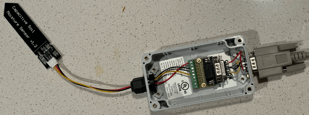
Sensor Adapter Box
I built a D_Sub 9 adapter box for easily swapping sensors in the future. It’s simply a cable gland that lets you connect a sensor to a D_Sub 9 breakout module connected to a D_Sub 9 pin panel mount connector.
D_sub 9 cable carries power to the sensor adapter and outputs the Sensor signal back to the window comparator.

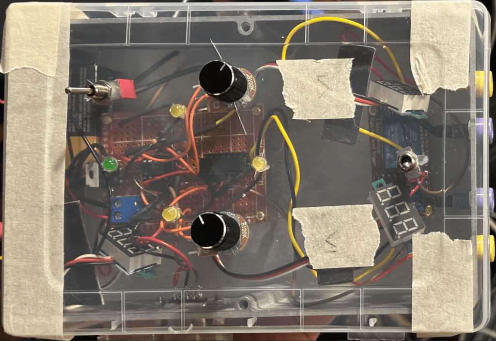
Prototype TEST
Here’s what the whole Prototype looks like.
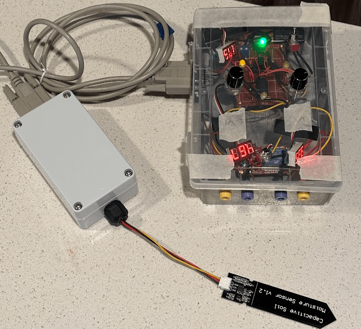
Increased capacitance in the moisture sensor (due to submersion in water) lowers signal voltage within adjusted range of a window comparator circuit (WCC). WCC sends a signal to Relay module which connects external voltage source (9V battery) to a load (white LED in series with 10k ohm resistor). Toggle switch allows to change relay module from NC to NO.
Final Build:
12/10/2024:
The temporary plastic lid was replaced with a permanent aluminum one. It looks professional from afar (I’m not great at cutting square holes).
I also removed to NC to NO switch so that instead of being in series with the positive output. It changes the logic of the relay module so that it can either be triggered by a low or high signal. The output is hard strapped to the NO relay so that if you turn off the box, the external supply will be disconnected no matter what.
Here’s a demo!
Battery life Issue:
The main problem with this design is that the battery lasts only about 3 hours. Additionally, the NO/NC switch only functions in the NC position (I’m not yet sure why). This creates a significant risk because when the battery dies, the relay closes, the pump is connected to power and floods the plants with water.
Fix:
Add a plug to the box to connect it to a 5V-12V AC to DC wall-adapter. If I include a normally closed relay and connect it’s coils to the wall power, it would connect the 9V battery into circuit and allow for ~3 hours of backup power when unplugged or during a blackout. I could also just replace the battery with an AC to DC adapter jack and make sure it’s always plugged in.

Leave a comment